STMAS
User Manual Version 002 BRUKER BIOSPIN 247 (327)
ent case is in the order of MHz so even a small deviation causes a severe broad-
ening in the STMAS spectrum. This can easily be understood as the rotational
echoes decay much more rapidly when the magic angle is off. Experimentally it
has been found that the precision for setting the angle must be ≤ 0.002°. The de
-
pendence on the accuracy is so important that the experiment itself must be used
to find the most precise magic angle setting. It is obvious that this can only be
done on a well-known sample, as we will see later in the chapter. In order to
achieve the necessary precision for the adjustability of the angle a special goni
-
ometer screw with an adapted gear transmission ratio is provided for the magic
angle setting knob as an upgrade for Bruker WB MAS probes. Once the best an
-
gle setting is found it is advisable to leave the probe in the magnet. Sample
changes, however, on the WB probes doesn’t change the setting noticeably.
Pulse Sequences 19.2
Figure 19.2. and Figure 19.3. show two of the basic sequences, which are 4-
pulse sequences with z-filter (stmasdqfz.av and stmasdqfe.av). Both sequences
start with a non-selective excitation pulse p1 that creates SQ coherency on the in
-
nermost ST which is allowed to evolve during the evolution period D0. Shortly be-
fore the end of the t
1
period there is a selective 180° pulse P4. This provides a
double quantum filter by which magnetization of the CT transition is eliminated
which will otherwise give a strong diagonal signal from a CT –> CT coherence
transfer pathway. The t
1
period is terminated with the second non-selective pulse
P2.
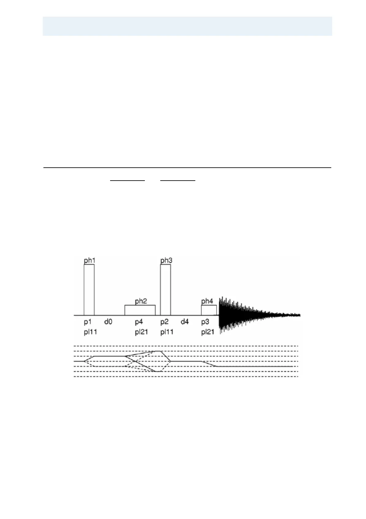
Figure 19.2. Four-pulse sequence and coherence transfer pathway for the double
quantum filtered STMAS experiment with z-filter (stmasdqfz.av)
Pulses p1 and P2 are non-selective pulses. The corresponding power level PL11
should be set to achieve around 100 kHz RF field amplitude. P3 and P4 are CT
selective pulse 90° and 180° pulses of about 20 and 40 µs, respectively, corre
-
sponding to an RF field amplitude of a few kHz. Delays D0 and D4 are the incre-
mented delay for t
1
evolution and 20 µs for z-filter, respectively. Phase lists are as
follows, for phase sensitive detection in F1 the phase of the first pulse must be in
-
cremented by 90° in States or States-TPPI mode: