Basic MQ-MAS
User Manual Version 002 BRUKER BIOSPIN 223 (327)
the limits are at least as large as the spectral width to allow baseline correction of
the whole spectrum. The “F1 shift in ppm” allows shifting the spectrum (including
its axis) in the vertical direction for cases where peaks are folded due to a limited
spectral window in a rotor synchronized experiment. For the first processing both
prompts are typically returned. At the end of the processing the AU program cor
-
rects the apparent spectrometer frequency of the indirect dimension by a factor
⎜R-p ⎜, where R is defined in equation [1] and p is the order of the experiment (e.g.
3 for 3QMAS):
(Eq. 17.1)
This ratio is calculated from the spin quantum number I of the nucleus and the
magnetic spin quantum number m, which is determined by the experiment, e.g. 3/
2 in case of a 3Q experiment of an order p=3. The program stores the “F1 shift”
that was calculated and will prompt for it when data are processed next time. If the
same F1 shift should be applied as before the AU program can be called with the
option “lastf1”. Before giving some further explanations about the experiment,
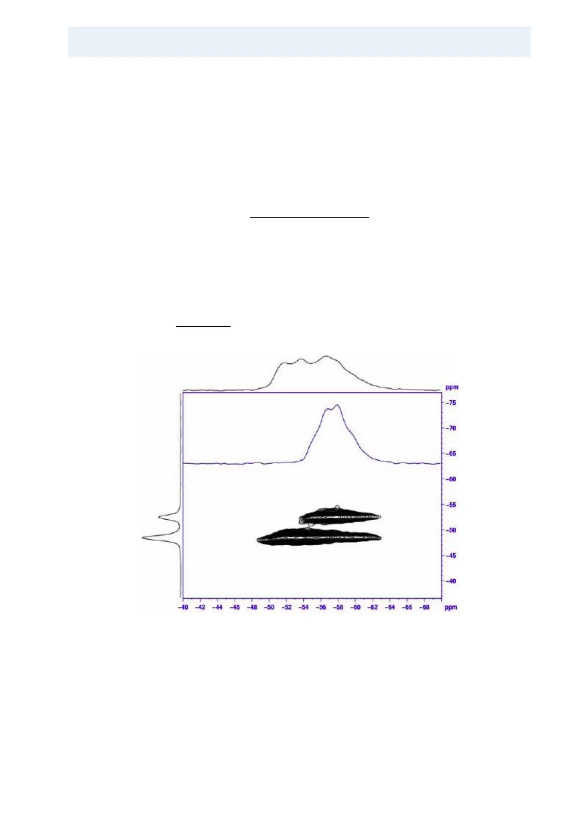
Figure 17.7. shows the 2D
87
Rb 3QMAS spectrum of RbNO
3
.
Figure 17.7. 2D
87
Rb 3QMAS Spectrum of RbNO3.
Top and left projections are the summations over the signal ranges. The spectrum
included in the 2D map is a cross section through the resolved peak resonating at
approximately 53 ppm. Note that at 11.7 T two of the three sites cannot be re
-
solved in the 2D spectrum. The spectral range shown in F1 corresponds to the
spinning frequency. Spectra are taken on AV500WB at a Larmor frequency of
163.6 MHz with a 2.5 mm CP/MAS probe, spinning at 25 kHz.
()
5.3118
)55.8)1(18(
2
−+
−−+
=
II
mIIm
R