Connections for Probe Identification and Spin Detection
User Manual Version 002 BRUKER BIOSPIN 25 (327)
Figure 3.12. Quadruple Resonance HFXY Experiment (WB probes ≥ 400 MHz
only!)
Connections for Probe Identification and Spin Detection 3.4
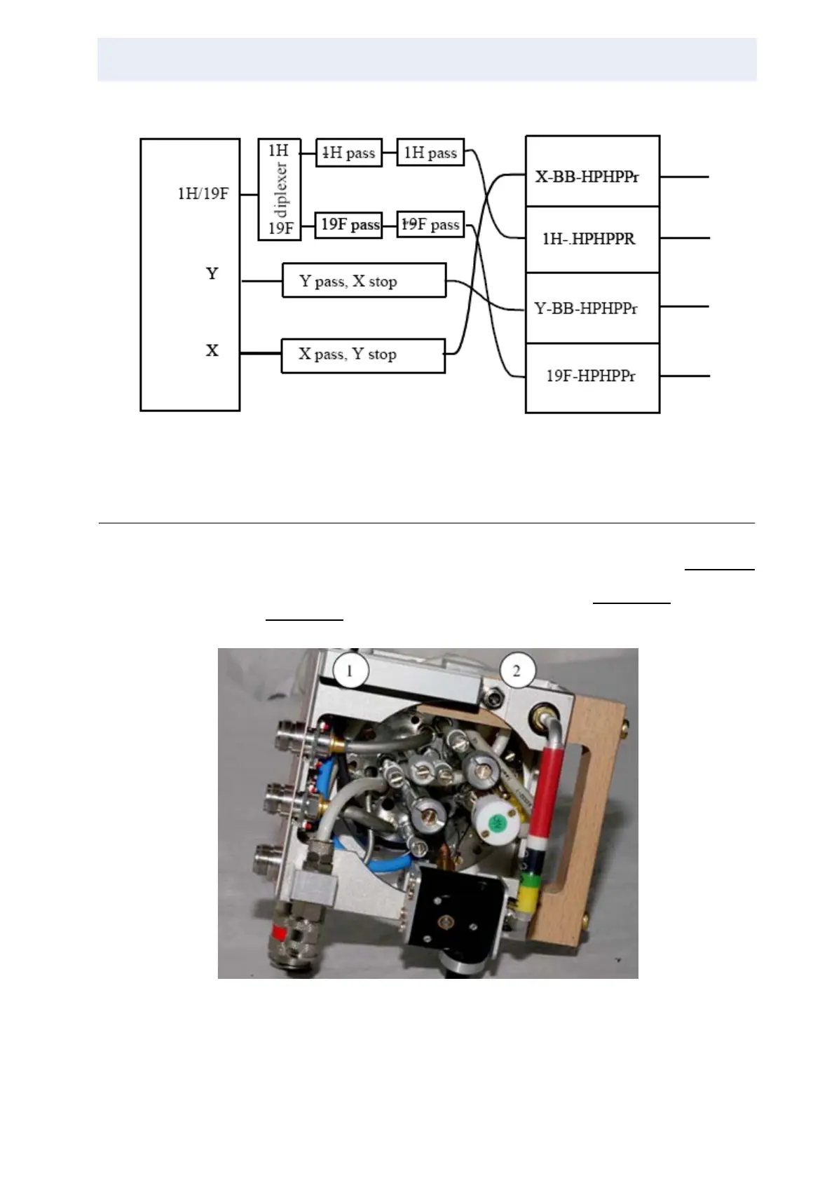
Most solids probes were delivered without Probe Identification System (PICS).
Probes delivered since 2007 are equipped with PICS. Please refer to Figure 3.4.
to identify the PICS port at the preamplifier cover module. The probe connections
for the spin rate cable and the PICS cable are shown in Figure 3.13.
for a WB and
in Figure 3.14.
for a SB probe.
Figure 3.13. PICS Probe Connector and Spin Rate Monitor Cable on a WB Probe
1. PICS probe connector
2. Spin rate monitor cable