Probe Setup, Operations, Probe Modifiers
User Manual Version 002 BRUKER BIOSPIN 45 (327)
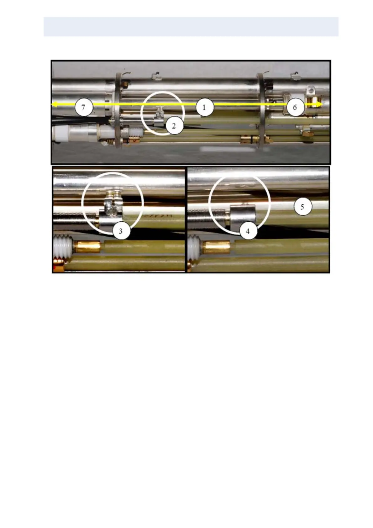
Figure 3.35. λ/4 (low range) and λ/2 Mode (high range), 400 MHz Probe
At 400 MHz, the wavelength is large, so the λ/4 point is below the closed section
(7) of the λ-line. At higher frequencies, the λ/4 point may fall within the closed sec-
tion 7.
The proton channel (decoupling channel) is usually tuned via a so-called λ-line
(“transmission line”). This is just a coaxial cable or a coaxial conductor with an ar-
rangement of an outer conductor (a tube) and an inner conductor (a rod). The rel-
ative diameters and distances and also the dielectric in between (usually air in WB
probes) determine the impedance of the transmission line. Since such a line is as
well an inductance as a capacitance, it is a resonating circuit. If the length of the
transmission line equals λ/4 or λ/2 of the RF-wave, it is a λ/4 or λ/2 line. Since the
upper end of the transmission line (inner conductor) is connected to the coil, high
voltage is required there. This means that the λ/4 point has low voltage but high
current, whereas the λ/2 point is at high voltage and low current. A short between
1. λ-line inner conductor
2. Rotating switch at λ/4 position
3. Switch closed rotating counterclockwise (seen from probe lower end). Contact springs
(grounded) touch the λ-line at the λ/4 position
4. Switch open rotating clockwise.
5. Switch operating rod
6. Tuning capacitor at the end of the λ-line inner conductor: Fine tunes the effective length and there-
fore resonating frequency of the λ-line. This tunes the proton channel frequency (“tune”).