Basic Setup Procedures
User Manual Version 002 BRUKER BIOSPIN 59 (327)
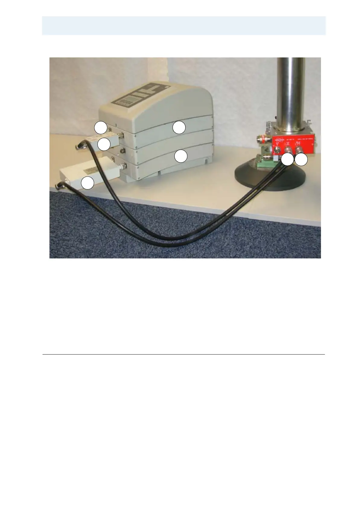
Figure 4.2. Probe Connections to the Preamplifier
The figure above shows the probe connections to the preamplifier with appropri-
ate filters, placed on a table for better illustration.
Setting Acquisition Parameters 4.2.2
Create a new data set for the experiment by typing edc in the command line.
1: X Low Pass Filter 5: 13C Matching Box
2: Proton Bandpass Filter 6: X Probe Connector
3: X-BB Preamplifier 7: 1H Probe Connector
4: 1H HP Preamplifier
1
2
6
7
5
4
3