258 (327) BRUKER BIOSPIN User Manual Version 002
Double-CP
6. Optimize decoupling and CP condition, run a reference
13
C CP/MAS spectrum
of the labelled glycine sample, using 16 scans. This reference spectrum will
serve to measure the efficiency of the DCP magnetization transfer.
7. To set up the conditions for the N to C transfer, one must define the RF field at
which the transfer is to take place, and find the appropriate power levels to
achieve these RF fields. In order to minimize losses due to insufficient excita
-
tion bandwidths and T
1ρ
relaxation, the contact should be executed at high
power. However, there are limitations in terms of what the probe can take, and
there are losses due to unwanted HH contact to the proton spin system. On
the other hand, in many samples (bio-samples) the spread of chemical shifts
that one wants to cover is not extremely wide or one even wants to execute the
transfer selectively (“Specific-CP”). An RF field of 35 kHz is a decent compro
-
mise. So, using the cp90 pulse program, and moving the carrier close to the
C
α
-peak, determine a power level pl11 which corresponds to 35 kHz RF (7.14
μsec 90 ° pulse). However, since the sample spins at 11 kHz, the HH condition
will require 46 or 24 kHz on one nucleus and 35 kHz on the other nucleus. If
you decide to account for the spin rate on the
13
C side, calculate the required
power levels for 24 and 46 kHz (= 35 kHz RF field +/- 11 kHz spin rate) RF field
using xau calcpowlev. Now the
13
C channel is set.
15
N Channel Setup 20.2.2
8. Create a new experiment using edc.
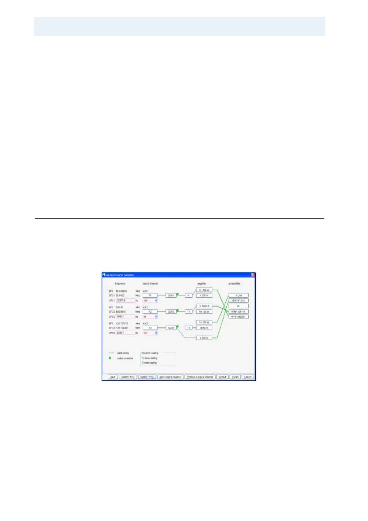
9. Setup the proper routing by going into edasp. Click the switch F1/F3 button to
get
15
N on channel 1.
Figure 20.3. Routing table for triple resonance setup change for
15
N pulse param-
eter measurement and CPMAS optimization.
10. If available, set pl1 and sp0 for a proton/
15
N HH condition in triple mode. On a
labelled sample, even the previous settings for
13
C should give a signal which
allows optimizing the HH condition.
11. When the HH condition is optimized, find the power level to achieve a 35 kHz
RF field (7.14 μsec 90 ° pulse, carrier close to the
15
N-resonance). It is essen-
tial to optimize the first proton to nitrogen HH contact. This is not as trivial as