46 (327) BRUKER BIOSPIN User Manual Version 002
General Hardware Setup
inner and outer conductor at the λ/4 position enforces a low voltage/high current
and fixes a certain resonance frequency.Some probes are tuned for the proton
resonance frequency by a tunable capacitor at the end of the λ/2-line (400 MHz
and up) which changes the effective length of the λ/2-line. Some probes (400 MHz
and below) are tuned by shifting the position of the λ/4 short to a higher (higher
frequency, shorter length) or lower (lower frequency, longer length) position.
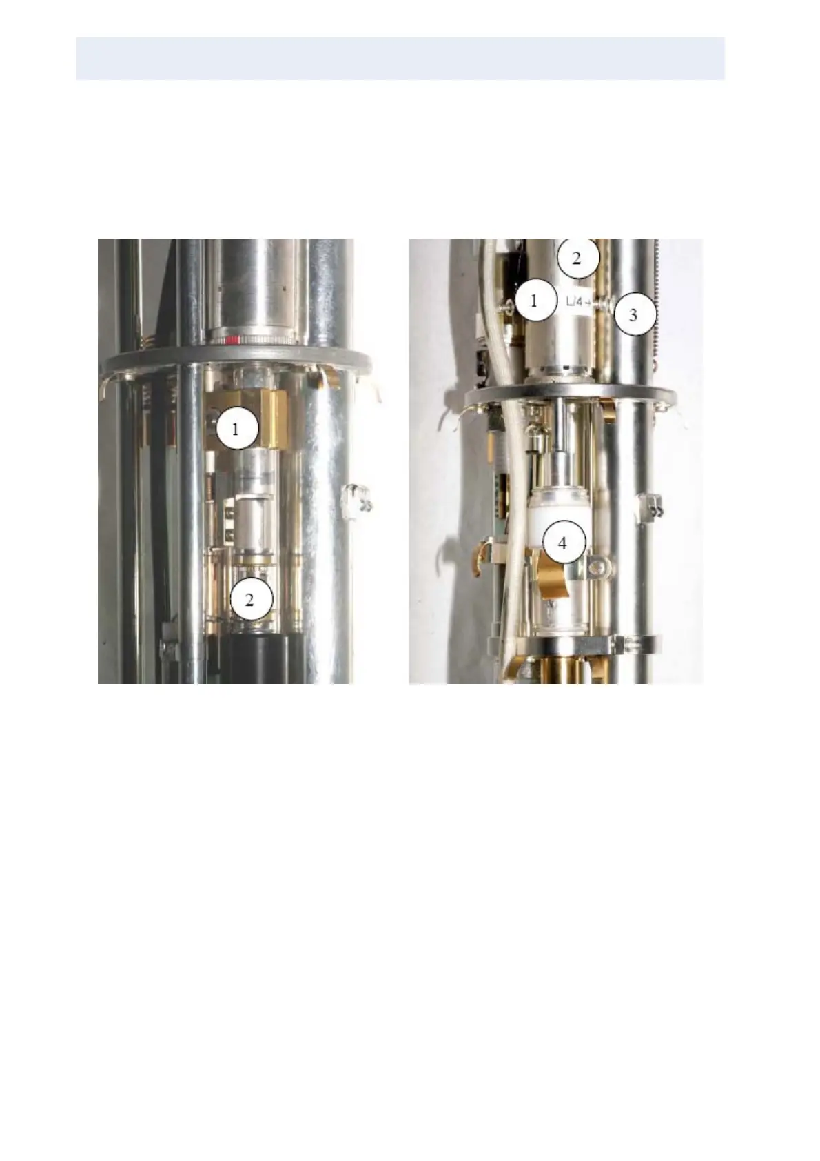
Figure 3.36. A λ/4 only probe (left) and a λ/4 - λ/2 probe (right)
On the left side of the figure above is a λ/4 only probe (200, 300 MHz, 400 low
range only probes). The transmission line is only λ/4, proton tuning is done by
moving the brass block to ground (1). Proton matching is done with capacitor 2.
On the right side of the figure above is a λ/4 - λ/2 probe 600 MHz. Due to the high
proton frequency the λ/4-length shortens, the λ/4 point (1) moves inside the trans-
mission line outer conductor (2). The screw (3) is used to set λ/4 (screw in) and λ/
2 –mode (screw out). (4) proton tuning capacitor.