16 (327) BRUKER BIOSPIN User Manual Version 002
General Hardware Setup
(High Power Low Noise Amplifier) which is strictly frequency selective, either
19
F
or
1
H.
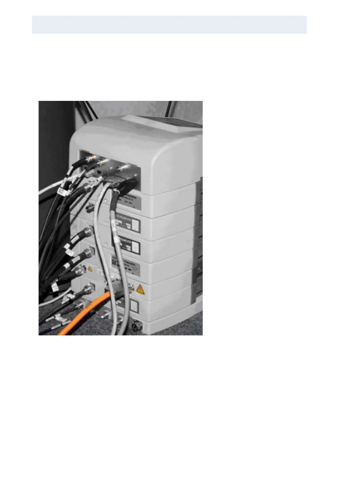
The connections into (the back) of the preamp stack should normally not be
changed. For broadband high power preamplifiers, it is important to insert the ap-
propriate “matching box” into the side of the preamp.
Figure 3.1. All Connections to the Back of the Preamplifier
RF cables from transmitter, RS-485
control, DC voltages in, tune and lock
RF in, RF signal out to receiver, gate
pulses for preamplifier control (multi-
receive setup only).
The orange colored cable is the high
voltage supply for the HPLNA pream-
plifier.