42 (327) BRUKER BIOSPIN User Manual Version 002
General Hardware Setup
3. Select the Q value of the insert according to the expected line widths (higher Q
for line widths up to 100 kHz). Please note that multiturn coils, especially multi-
filament coils, have an intrinsically low Q.
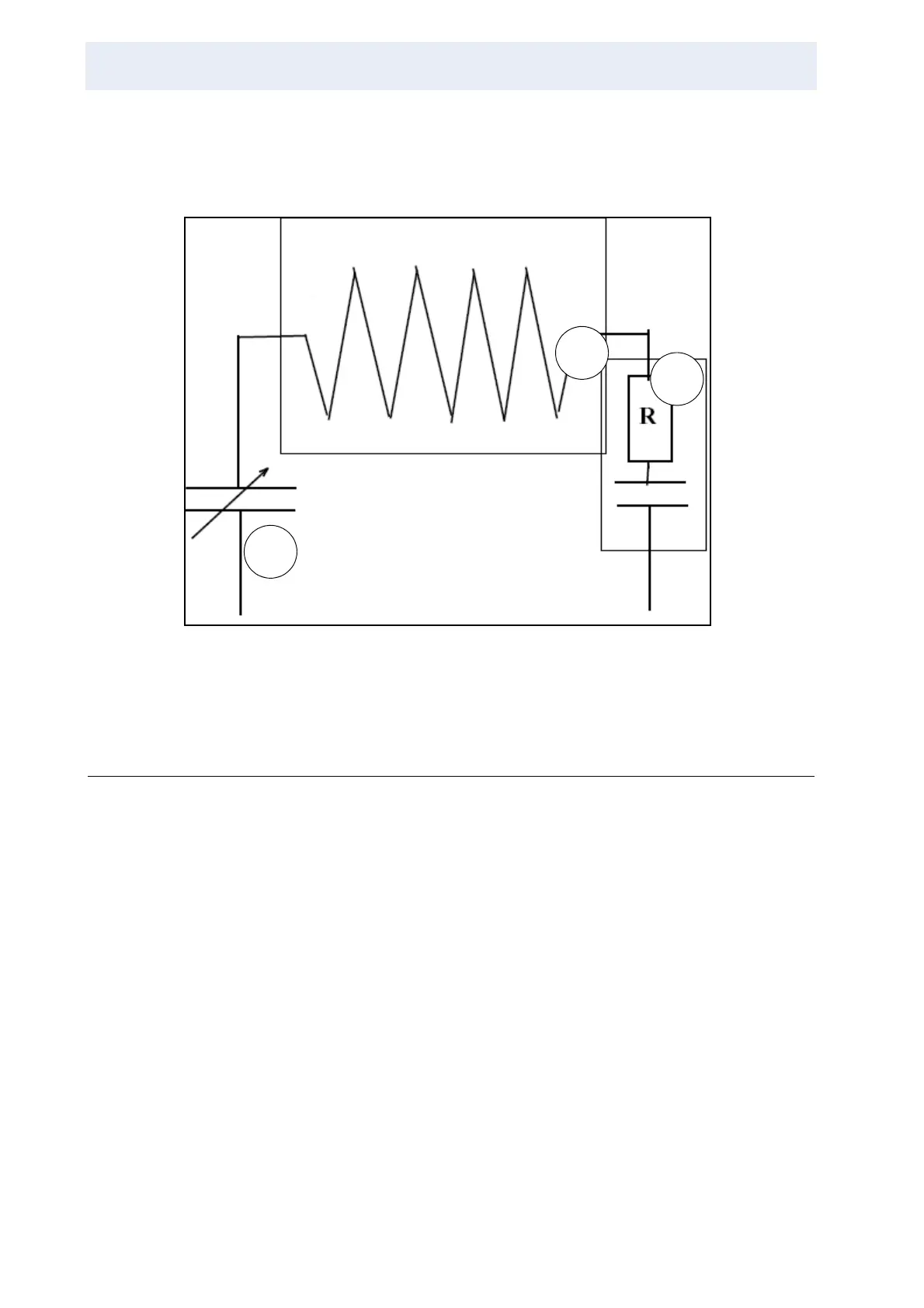
Figure 3.33. RF Setup of a Wideline Single Frequency Probe
Shifting the Probe Tuning Range 3.7.2
Most probes cover a fairly wide frequency range. Changing the frequency range
of a probe requires either a change in the inductance or capacitance of the circuit.
The inductance of a circuit is hard to change unless a coil is mechanically length-
ened or shortened. Most probes are tuned over a certain range by variation of a
capacitance. The frequency range is then determined by the minimum and maxi-
mum capacitance that can be set. In order to make the inductance as high as pos-
sible (since the signal from the oscillating magnetization is detected in the
inductive part), one usually chooses a capacitance with very small minimum ca-
pacitance, which again means a not large enough maximum capacitance. So in
most probes additional tuning components must be inserted (removed) to achieve
the full tuning range. The highest signal to noise is always reached with maximum
inductance and minimum capacitance, i.e. at the high end of the tuning frequency
achieved with maximum inductance.
1. Tuning capacitance
2. Exchangeable NMR coil
3. Exchangeable symmetrization and Q-reduction
1
2
3