Practical CP/MAS Spectroscopy on Spin 1/2 Nuclei
User Manual Version 002 BRUKER BIOSPIN 101 (327)
Possible Approaches for Non-13C Samples 6.3
If an arbitrary X-nucleus of spin ½ is under investigation (quadrupolar spins must
be treated separately), the strategy follows the one described above, if the sample
contains the protons bound to
13
C. In this case, running a
13
C cp/mas spectrum
allows setting and determining all proton parameters (recycle time, contact time)
from the
13
C setup. To run the X-nucleus, cross polarized from protons, one just
needs to set the HH-condition from the known proton RF-field, the spin rate, and
the transmitter power at the NMR-Frequency of the X-nucleus such that the effec
-
tive field at the X-frequency equals the effective field at proton frequency ±spin
rate.
Example: setting the HH-condition for
15
N from known parameters for
13
C-CP/
MAS. The gyro-magnetic ration of
15
N is lower by a factor of 2.5 compared to car-
bon (proton frequency: 400 MHz,
13
C-frequency: 100 MHz,
15
N frequency: 40
MHz). The probe efficiency is about the same for
13
C and
15
N (but not
1
H!), so
one needs about 2.5 times higher RF-voltage for the 15N-contact pulse than for
the
13
C-contact pulse, if the spin rate and the proton RF-field are the same. This is
equivalent to 2.5
2
=6.25 times the power in watts! So if ased shows pl1W =150W
for a well optimized 13C-CP setup,
15
N will require 6.25*150 W= 938 W! This is
far above specs, so the same proton contact power level cannot be used, it needs
to be lowered. The maximum allowed power for a contact pulse on
15
N is 500W.
This means that the proton contact power should be lowered by approximately a
factor of sqrt (938/500) ≈1.37. Precalculating power levels like this will get the pa
-
rameters close enough to see a cp-signal on a good test sample, so further opti-
mization is possible. See "Test Samples" for suitable test samples.
The most efficient way of precalculating power levels for multi-nuclear spectrosco-
py is the following:
1. Determine the power conversion factor for some nuclei of interest on a suitable
test sample, from the low end to the high end of the probe tuning range. This
means measuring a precise 360° pulse (make sure it is 360°, not 180° or
540°!) and the associated power level. Make a table in your lab notebook as
follows (see
"Appendix"):
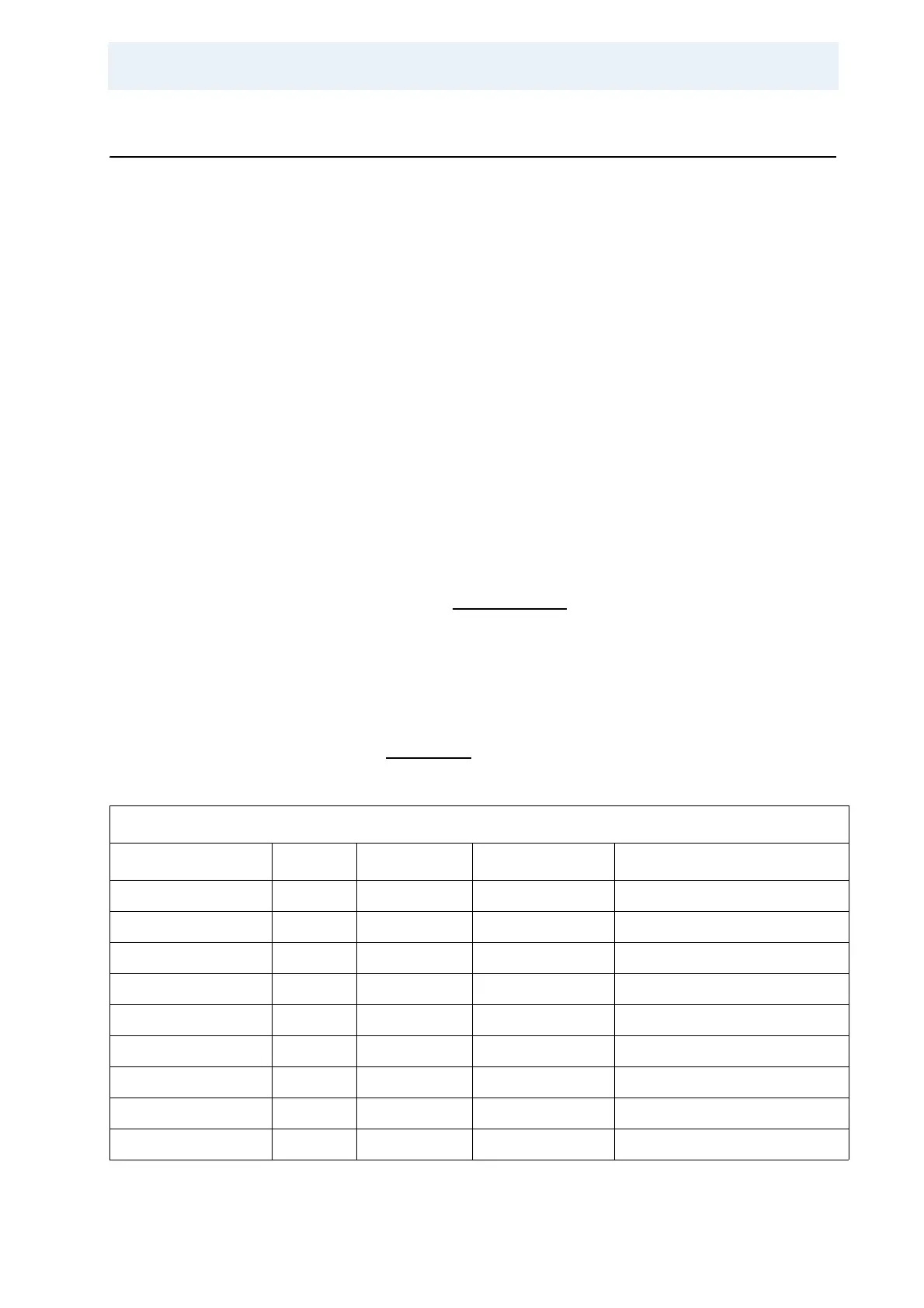
Table 6.1. Power Conversion Table
Probe: 4mm Triple
Nucleus Frequency P90 (µs) Rf-field (Khz) Power (W or dB) Remarks
1
H/400.13 2.5 100 100 Low range
19
F/376.3 Not available
15
N/40.5 6.5 38.6 300 Probe in double mode
15
N/40.5 6.5 38.6 500 Probe in triple mode C/N
29
Si/79.5 6 41.7 300 Double mode low range
13
C/100.5 4 62.5 150 Double mode low range
13
C/100.5 5 50 200 Triple mode C/N
119
Sn/149.1 4 62.5 100 Double mode high range
31
P/161.9 3.5 71.4 150 Range switch up, double mode