26 (327) BRUKER BIOSPIN User Manual Version 002
General Hardware Setup
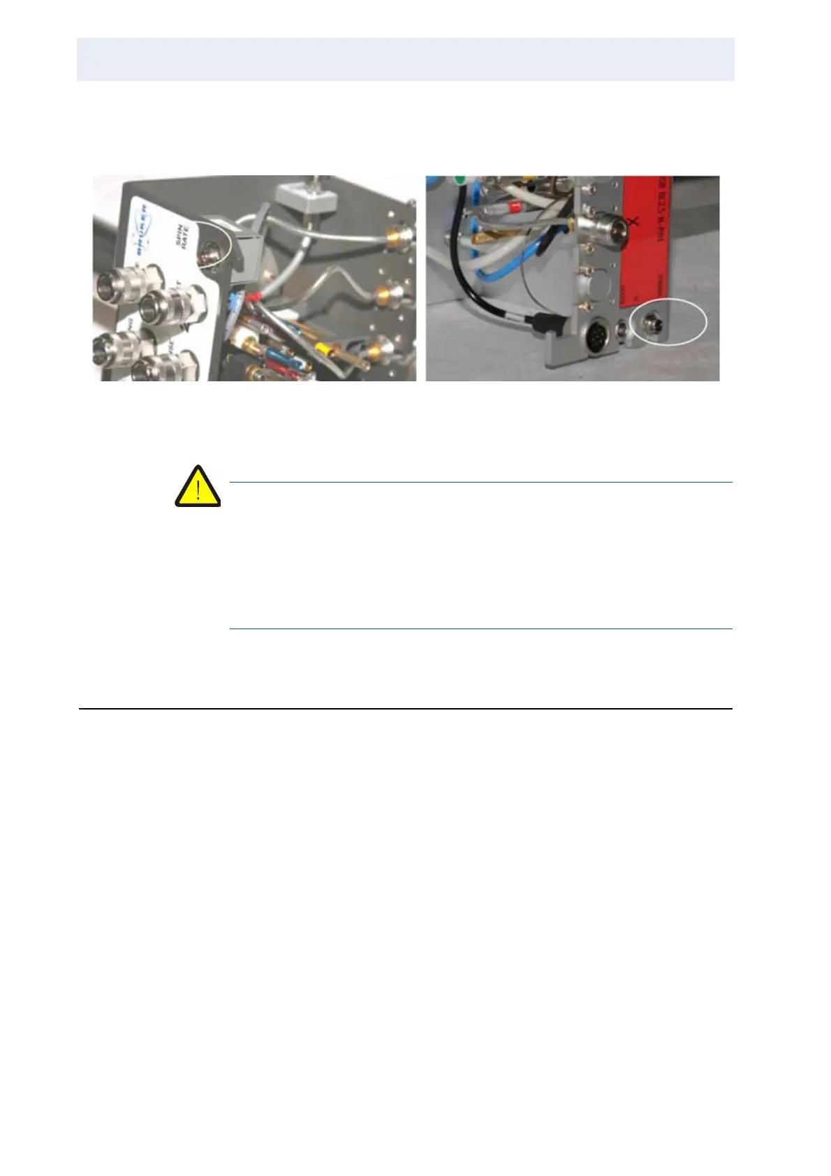
On SB probes the location may differ, but the connectors are (if present in the
case of PICS) easily identified by the type of connector.
Figure 3.14. Spin Rate Monitor Cable Connector for 2 Different Types of SB
Probes
Warning: The spin rate monitor cable has a probe side connector that is ex-
actly the same as the power supply cable for the B-TO thermocouple oven
used with many high resolution probes. If this cable is connected to the
spin rate monitor assembly at the probe, the latter will be destroyed. Make
sure the B-TO cable and the MAS cable (labelled “probe” at the probe side)
are labelled such that they cannot be mistaken!
MAS Tubing Connections 3.5
For any type of fast spinning probe, compressed gas is used to provide the spin-
ner bearing and drive gas. Please refer to the installation or site planning manuals
to learn about the gas requirements. The most important parameters are:
• Mains pressure (should be at least maximum required pressure +1 bar, to pro-
vide pressure regulation range).
• Bearing pressure: up to 4.5 bar (as of February 2008)
• Drive pressure: up to 4.5 bar (as of February 2008)
This means that at least 5.5 bars of pressure should be available at the outlet. If
the pressure droop along the supply tube is substantial, the internal pressure may
drop below 5 bars, then the MAS unit stops to regulate and gives a warning.
Consequently, we recommend a primary (inlet) pressure of min. 6 bar, preferably
7-8 bar (max. 10 bar) and a low loss gas line (8mm inner diameter, distance ≤5
meters) between the instrument and the gas supply, to assure trouble free opera-
tion even under conditions of high gas throughput. The maximum throughput de-
pends on the experimental conditions and the probe type.