218 (327) BRUKER BIOSPIN User Manual Version 002
Basic MQ-MAS
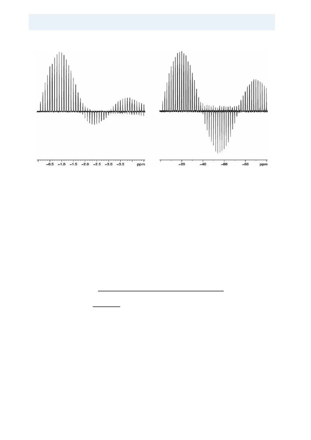
Figure 17.4. Nutation profiles of selective and non-selective pulses.
Left diagram shows signal intensity of
87
Rb resonances in RbNO3 as a function of
a non-selective pulse at approx. 150 W RF power, the right diagram shows the
signal intensity as function of a selective pulse at less than approx. 0.5 W. Spectra
are taken on AV500WB at a Larmor frequency of 163.6 MHz with 2.5 mm CP/
MAS probe spinning at 25 kHz. Note the different scaling of x-axis, which is dis
-
played as “ppm” but corresponds to the used pulse lengths in µs (apart from the
sign).
Once the central transition selective 90° pulse is calibrated the parameters can be
copied to a new data set with iexpno, and the MQMAS pulse program can be
loaded. Available pulse programs are mp3qzqf and mp3qzfil. The first is a 3-pulse
sequence, the second a 4-pulse sequence. The sequence with fewer pulses will
be slightly more sensitive, whilst the 4-pulse sequence can be used as an initial
set-up for experiments with sensitivity enhancement methods like DFS or FAM
(see
"MQ-MAS: Sensitivity Enhancement" on page 231 describing sensitivity
enhancement methods).
In Table 17.2. the starting parameters for the set-up are displayed. This table
gives typical values for the pulses and powers that should be close to the final val-
ues confirmed by the optimization procedure. Parameters like O1, TD, SWH, RG,
should already be set in the standard 1D spectrum. For 4 mm probes these pulse
lengths are about the limit of what can be achieved, for 2.5 mm probes somewhat
shorter pulses can be obtained. For I = 3/2 and I = 5/2 nuclei the ratio of p1/p2 ≈ 3.
For pl11 an initial value that corresponds roughly to 300 W can be used. Optimi-
zation will be done on the first increment of the 2D sequence, i.e. d0 = 1 µs. Two
strategies for the optimization procedure can be followed; either the pulse lengths
p1 and p2 or the power level pl11 can be optimized for maximum signal ampli
-
tude. However, the latter can be disadvantageous because a power level above
the probe limit might be applied, in order to clearly determine the optimum power.
In the case of 300 W amplifiers the maximum signal amplitude may not be ob
-
tained even at full power, with the chosen pulse lengths.