Basic Setup Procedures
User Manual Version 002 BRUKER BIOSPIN 57 (327)
Setting the Magic Angle on KBr 4.2
For all following steps, generate new data sets with appropriate names using the
edc command to record all individual setup steps.
RF-Routing 4.2.1
The spectrometer usually has 2 or more RF generation units (SGU's), transmitters
and preamplifiers. In order to connect the appropriate SGU to the appropriate
transmitter and the transmitter to the associated preamp where the probe chan
-
nels are connected, there are several routing possibilities. In order to minimise er-
rors in hardware connections, the routing is under software control where
possible. Where cable connections need to be done manually, the software does
not allow a change. These connections are made during instrument installation.
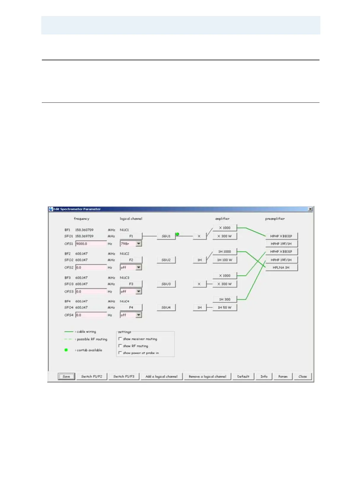
Enter the “edasp” command (or click the Edit button in the nucleus section in the
acquisition parameter window eda) in order to get the spectrometer router display.
Alternatively, click on the routing icon in eda.
Figure 4.1. Routing for a Simple One Channel Experiment
The figure above shows the routing for a simple one channel NMR experiment us-
ing the 1000 W output from the high power amplifier.
In this menu, 4 RF channels are available. These 4 RF channels can be set up for
4 different frequencies. The two left most columns labelled frequency and logical