252 (327) BRUKER BIOSPIN User Manual Version 002
STMAS
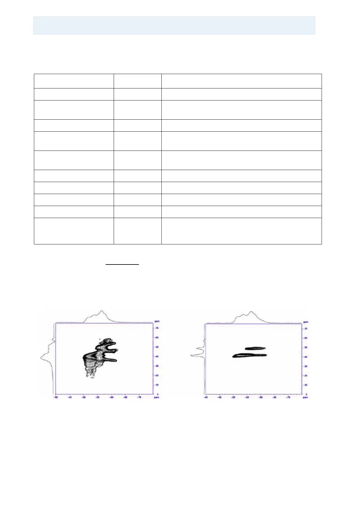
In Figure 19.4. two 2D plots of the
87
Rb STMAS experiment on RbNO
3
are com-
pared. The spectrum on the left was obtained after the first execution of the exper-
iment. The spectrum on the right was obtained after several iterations of resetting
the angle and rerunning the spectrum. From this it is obvious that the spectrum of
the sample for the setup must be known because otherwise it is impossible to
judge whether a shoulder or a splitting is due to an incorrectly set angle or another
signal from another site in the sample.
Figure 19.4. 87Rb STMAS Spectra of RbNO3
While the left spectrum has been obtained after adjusting the magic angle with
KBr, the right spectrum can be obtained after several iterations of readjusting the
angle and rerunning the 2Dspectrum.
Table 19.5. F1 Parameters for the 2D Data Acquisition.
Parameter Value Comments
F1 parameters: In eda.
FnMode States TPPI, or
States QF
2D acquisition mode for stmasdqfz.av.
2D acquisition mode for stmasdqfe.av.
TD see text Number of FID’s to be acquired.
SWH “masr” Equals spinning frequency for rotor synchronization, from
this IN0 is calculated correctly, if ND_010 is already set.
NUC1 Select the same nucleus as for F2 so that transmitter fre-
quency offset is correctly set (important for referencing).
Pulse program parameters: In ased.
D6 0 Used in stmasdqfe.av only.
IN6 =IN0*8/9 Used in stmasdqfe.av for I = 3/2.
D7 0 Used in stmasdqfe.av only.
IN7 =IN0*7/24
=IN0*28/45
=IN0*72/55
Used in stmasdqfe.av for I = 5/2.
Used for I = 7/2.
Used for I = 9/2.