52 • DM NAX® Product Manual — Doc. 9045M
Output Power Per Channel
Mode 1 Channel Driven 2 Channels Driven 3 Channels Driven 4 Channels Driven
Lo-Z, 8 Ω (single ended) 150 W 150 W 75 W
1
75 W
Lo-Z, 4 Ω (single ended) 200 W 150 W 75 W
1
75 W
Lo-Z, 8 Ω Bridged 300 W 150 W 150 W
1
N/A
Hi-Z 70V 300 W 150 W N/A N/A
Hi-Z 100V 300 W 150 W N/A N/A
NOTES:
l
Total output power from all channels combined (simultaneously) is up to 300 W.
l
Each mode will output power in watts up to the value listed in the table.
Connectors
CH1-CH4 (2) 4-pin 5.08 mm pitch, 12A plug with screw locking retainers;
Power amplifier output;
Terminals accept up to 12 AWG (3.31 mm)
NOTE: Output is direct-coupled, not transformer isolated.
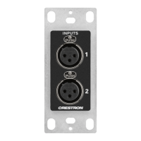
IN1-IN4 (4) 3-pin 3.5 mm detachable terminal block;
Balanced/unbalanced line or mic-level audio inputs;
Maximum Input Level: 8.7 Vrms, +21 dBu;
Input Impedance: 10k Ω Wake threshold is -65 dBu;
Phantom power is available when used as mic-level inputs
OUT1-OUT4 (4) 3-pin 3.5 mm detachable terminal block;
Balanced/unbalanced line-level audio outputs;
Maximum Output Level: 8.7 Vrms, +21 dBu
REMOTE (1) 2-pin 3.5 mm detachable terminal block;
Connect to dry contact closure to place amplifier in standby mode
G (1) 6-32 screw;
Chassis ground lug
100-240V~ 1.2-0.6A 50/60 Hz (1) IEC 60320 C14 main power inlet;
Mates with removable power cord, included
Ethernet 1 (1) 8-wire RJ45 female;
100Base-T/1000Base-TX Ethernet port
Ethernet 2 (1) 8-wire RJ45 female;
100Base-T/1000Base-TX Ethernet port
Controls and Indicators
PWR (1)LED;
White indicates amplifier is on and ready for use;
Amber indicates the amplifier is booting;
Red indicates amplifier is in standby
 Loading...