Chapter 4 Disassembly / Assembly and Adjustment
4.2 Removal / Replacement
4-18
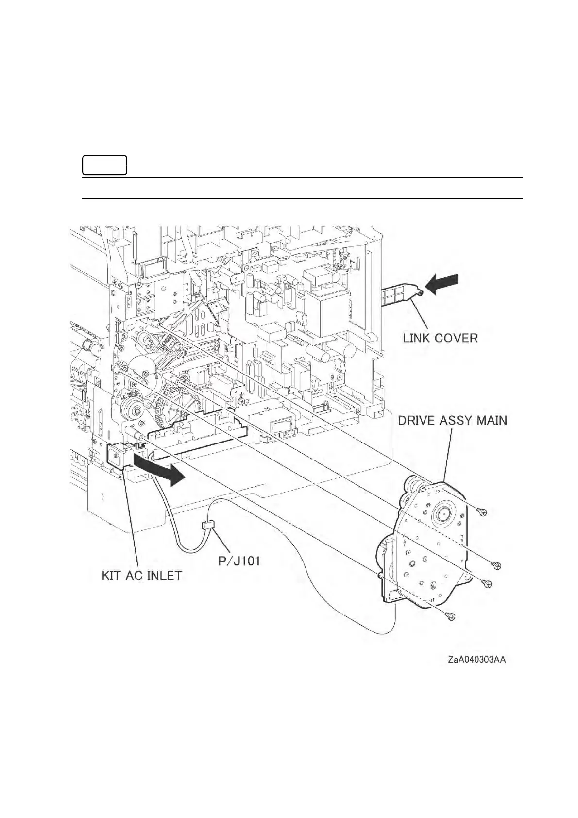
13 Move the KIT AC INLET (110 / 220) (PL18.2.99) and the harness guide slightly toward you.
14 Remove the four screws (silver, tapping, 8mm) that fix the DRIVE ASSY MAIN, and then remove
the DRIVE ASSY MAIN from the printer.
15 Disengage the connector (P/J101) from the DRIVE ASSY MAIN.
Keep the LINK COVER stowed within the printer.
 Loading...