Chapter 4 Disassembly / Assembly and Adjustment
4.2 Removal / Replacement
4-124
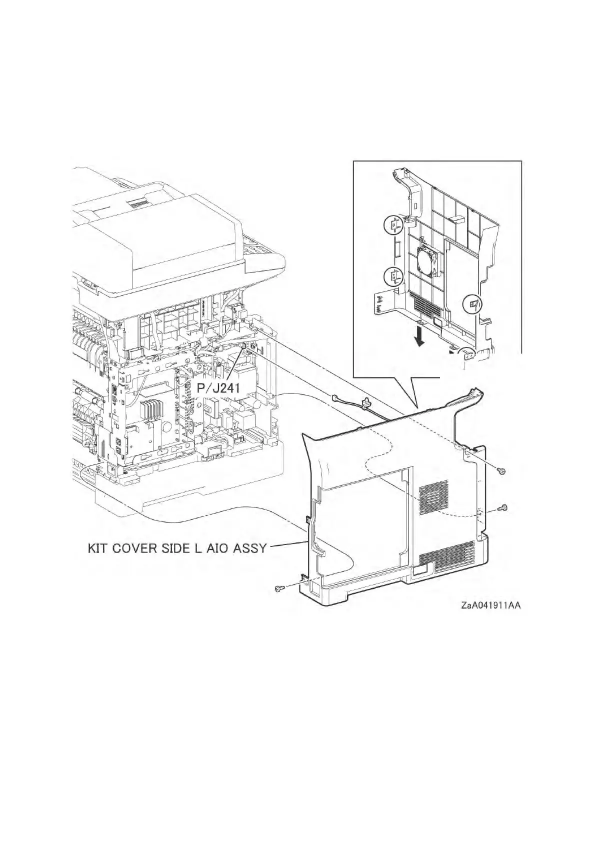
6 Remove the three screws (silver, tapping, 8mm) that fix the KIT COVER SIDE L AIO ASSY,
release the four holes from the bosses on the frame, and then remove the KIT COVER SIDE L
AIO ASSY.
7 Disengage the connector (P/J241) from the PWB LVPS, and then release the harness clamp
from the printer.
 Loading...