Chapter 7 Wiring Data
7.5 Interconnection Wiring Diagram of Parts
7-17
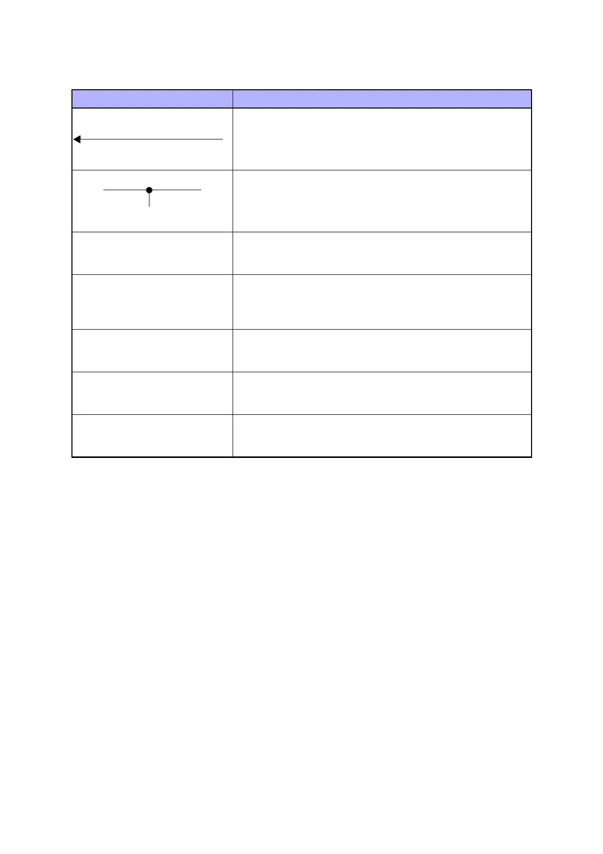
Denotes the function, and logic value of the signal when the func-
tion operated (Low: L, High: H).
The given voltage is for signal in high status.
The arrow indicates the direction of signal.
Denotes a connection between wires.
I/L +24VDC
Denotes DC voltage when the interlock switch in HNB MCU
WITH CPU turns on.
+5VDC
+3.3VDC
Denotes DC voltage.
SG Denotes signal ground.
AG Denotes analog ground.
RTN Denotes the return.
Table 7-3
Symbols Description
EXIT PAPER SENSED(L)+3.3VDC
 Loading...