Chapter 7 Wiring Data
7.5 Interconnection Wiring Diagram of Parts
7-21
LVPS overcurrent protection circuit
Each output (+24VDC, +5VDC,+3.3VDC) of LVPS stops all outputs if it is shorted to ground or between
ground.
LVPS overvoltage protection circuit
Each output (+24VDC, +5VDC,+3.3VDC) of LVPS stops all outputs if there is overvoltage.
The operating voltage of the overvoltage protection of each output is as following:
+24VDC: 27VDC~36VDC
+5VDC: 7VDC
+3.3VDC: 4.6VDC
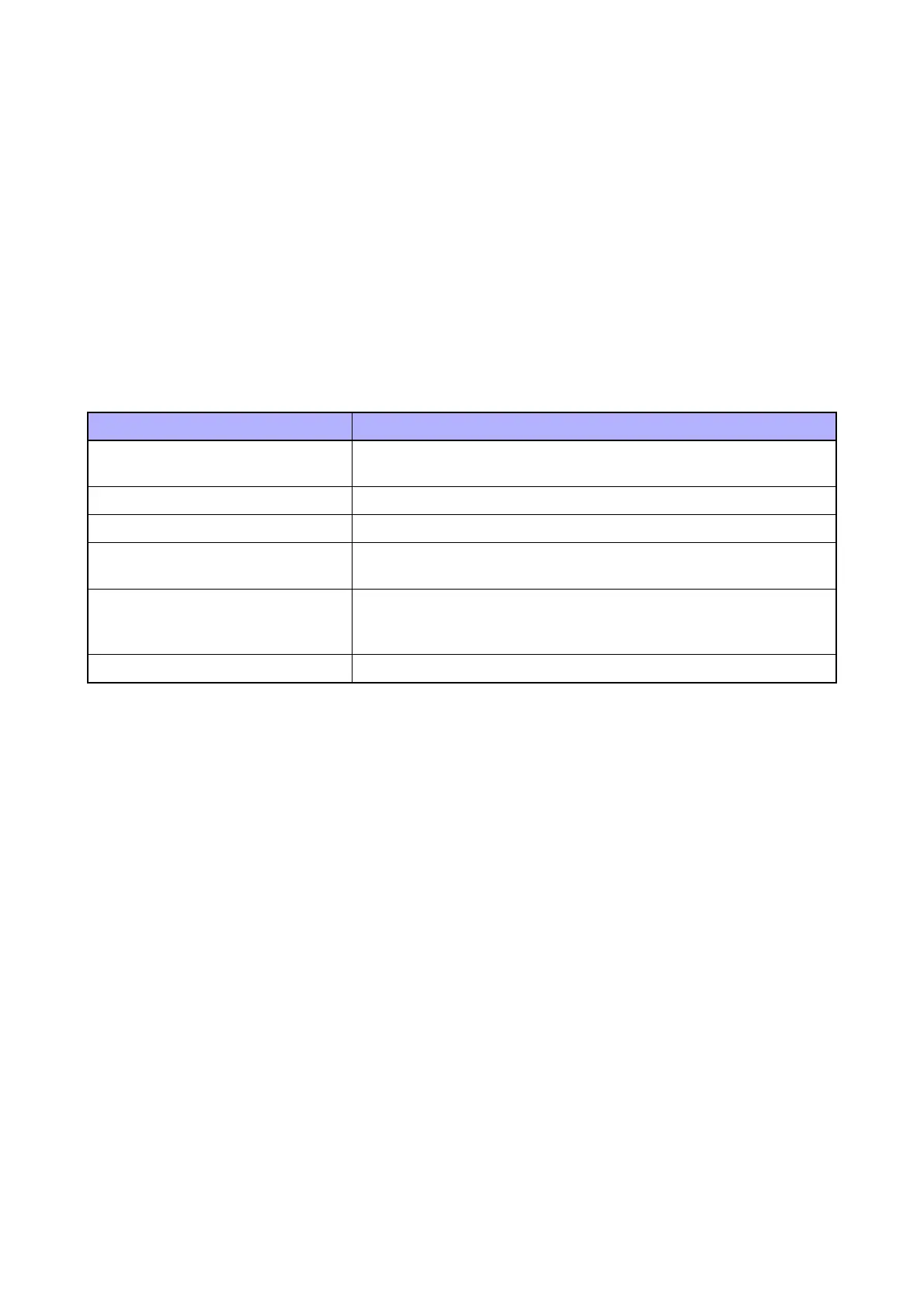
Table 7-4
Signal line name Description
HEAT1
HEATEN
Control signal of the Heater
I/L R OPEN The Open/Close Detection Signal of the Rear Cover
I/L F OPEN The Open/Close Detection Signal of the Front Cover
ALM LV FAN
LV FAN STOP
Control signal of the LVPS FAN
ALM R FAN
R FAN LOW
R FAN STOP
Control signal of the Rear Fan [FAN SUB]
RDY PWR ON Control signal of the LVPS
 Loading...