D
IRECTION FR091521, REVISION 1 VIVID S60N/VIVID S70N BASIC SERVICE MANUAL
8-76 Section 8-4 - Cables - Replacement Procedures
PRELIMINARY
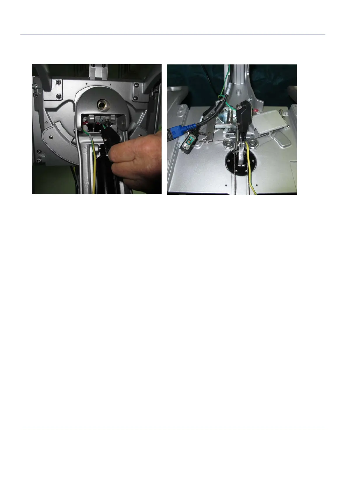
6.) Thread the OPIO to BIF cable from below the OPIO platform to emerge above the platform - see
Figure 8-98 below.
8-4-1-5-2 Securing the Cable to the Chassis
NOTE: Once the cables have been laid out throughout the system, the next step is to secure the various cables
in position using the cable holders previously removed and replacing the tie-wraps.
1.) Return the cable tie-wrap to the upper section of the lower arm
- see Figure 8-88 on page 8-70.
2.) Return the two cable bracket holders - two securing screws in each bracket - one bracket on either
side of the gas spring - see Figure 8-85 on page 8-68.
3.) Return the white cable supporting bracket to its position on the central column to secure the cables
as shown in Figure 8-84 on page 8-68.
4.) Secure the lower section of the lower arm to its position on the central column and secure it in
position by inserting the two securing shafts previously
removed - refer to Figure 8-81 on page 8-66.
5.) Secure each shaft in position with the cir-clips previously removed.
6.) Supporting the OPIO platform with one hand, using the shaft previously removed, attach the upper
section of the lower arm to the upper arm - refer to Figure 8-79 on page 8-65
and Figure 8-80 on page 8-66.
7.) Return the lower arm securing screws to secure the shaft - refer to Figure 8-78 on page 8-65.
8.) Secure the "up-down shaft" previously released - refer to Figure 8-87 on page 8-69.
9.) Return the OPIO to its position on the OPIO platform as described in Operator Panel Keyboard
Assembly Installation Procedure on page 8 - 47.
10.)Secure the cables in the lower section of the articulated arm with tie-wraps as
shown in Figure 8-74 on page 8-63.
11.)Continue and secure the cables in the articulated arm as shown in Figure 8-73 on page 8-62.
12.)Return the cable holders on the articulated arm previously
removed - refer to Figure 8-72 on page 8-62.
13.)Return the articulated arm service covers to their appropriate locations on the articulated arm.
Figure 8-98 Feeding the OPIO-to-BIF Cable through the OPIO Aperture

 Loading...


