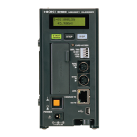
12.1 General Specifications
217
Chapter 12 Specifications
12
Display
Trigger
Display Type LCD
Display Resolution 16 characters x 2 lines, 5 x 8 dots/character
Display Content • Display of measurement values, number of measurement data items, and event
marks
• Display of time, master/slaves, available CF card space, serial/version number, IP
address, and MAC address
• Display of errors and warnings
(Each press of toggles the above display content and cancels display)
LED An LED that emits two colors allows for identifying when a compact flash card can be
ejected, and when it is being accessed
Lit green : Recording to the CF card is possible
Lit red : The CF card is being read
Off : The CF card can be ejected
Trigger System Digital comparison
Trigger Mode Single, continuous
Trigger Timing Start, stop, start and stop
Trigger Sources • Analog inputs
Connecting multiple 8948 Voltage/Temp Units and 8949 Universal Units allows for a
maximum of 120 channels
• Pulse totalization inputs
Connecting multiple 8996 Digital/Pulse Units allows for a maximum of 120 channels
• Logic inputs
Connecting multiple 8996 Digital/Pulse Units allows for a maximum of 120 channels
External Triggers A trigger is applied on the rise or fall of an external input signal
(rise and fall are selectable)
• Rise
A trigger is applied when an input signal rises from a LOW of 0 to 1.0 V to a HIGH of
2.5 to 5.0 V
•Fall
A trigger is applied when the external trigger terminal is shorted with the GND or
when an input signal falls from a HIGH of 2.5 to 5.0 V to a LOW of 0 to 1.0 V
VInput voltage range : -5 to 10 VDC
External trigger filter : ON and OFF are selectable
Response pulse width : When the filter is OFF, the HIGH period is 1 ms or more and
the LOW period is 2
μs or more
When the filter is ON, the HIGH period is 2.5 ms or more and
the LOW period is 4 ms or more
External trigger input terminal: Push-button type terminal block
Trigger Conditions OR and AND of each trigger source. A trigger condition can be set separately for each
channel
Trigger Types
(Analog and Pulse) *1, *2
• Level trigger
A trigger is applied when the signal rises (falls) to the set level value
• Window trigger
A trigger is applied when the signal exits or enters the area set by the trigger level
upper limit and lower limit
*1: When the 8948 Voltage/Temp Unit or 8949 Universal Unit is connected
*2: When the 8996 Digital/Pulse Unit is connected
Trigger Type (Logic) *2 1, 0, and x pattern triggers (x = any state)
Trigger Level Resolution (Analog) 0.1%f.s. (f.s. = 10 divisions)
(Pulse) Integration 1c, revolution 1/n (where n = pulses/rev)
Pre-trigger Time setting (any)
This can also be set when real-time saving

 Loading...