3.8 Connection Method for External Control Input Terminals
50
Inputting a signal from an external device enables the input signal to be a trigger
source, and measurement to be started and stopped. Furthermore, you can col-
lect data (external sampling) at any timing with which you want to measure.
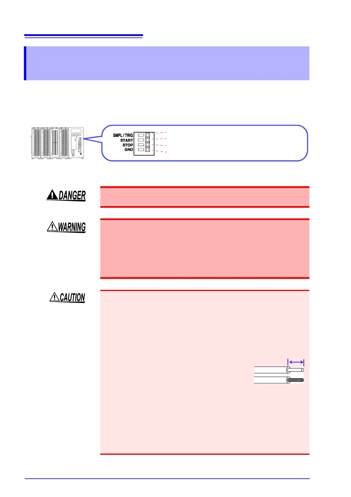
3.8 Connection Method for External Control
Input Terminals
This allows a sampling trigger to be input. (p. 81)
This allows a measurement start signal to be input.
This allows a measurement stop signal to be input.
This is the GND terminal.
To avoid electrical hazards and damage to the instrument, do not apply voltage
outside of the range (DC -5 to 10 V) to the External control input terminals.
To avoid electric shock or damage to the equipment, always observe the follow-
ing precautions when connecting to External control input terminals
.
• Always turn off the power to the instrument and to any devices to be connected
before making connections.
• Be careful to avoid exceeding the ratings of external terminals and connectors.
• Ensure that devices and systems to be connected to the External control input
terminals are properly isolated.
• The GND of the external control input terminals and the GND of the Memory
HiLogger main unit are not commonly insulated. To avoid damaging the instru-
ment, make sure wiring is done in such a manner that no potential difference
can result between the GND of the external control input terminals and the
GND of the equipment or device to be connected.
• To avoid electric shock, use the recommended
wire type to connect to the current input termi-
nals, or otherwise ensure that the wire used has
sufficient current handling capacity and insula-
tion.
Recommended wire
Single strand: 1.0 mm dia. (AWG 18)
Multi-strand: 0.75 mm
2
(AWG 20)
Acceptable limits
Single strand: 0.4 to 1.0 mm dia.
(AWG 26 to 18)
Multi-strand: 0.3 to 0.75 mm
2
(AWG 22 to 20)
Strand diameter: minimum 0.18 mm
Standard insulation stripping length: 10 mm
Button pressing tool: Blade screwdriver (tip width 2.6 mm)
Single strand
Multi-strand
10 mm