3.8 Connection Method for External Control Input Terminals
51
7
3
Chapter 3 Setting Up the Instrument
Required tools: Flat blade screwdriver............... 1
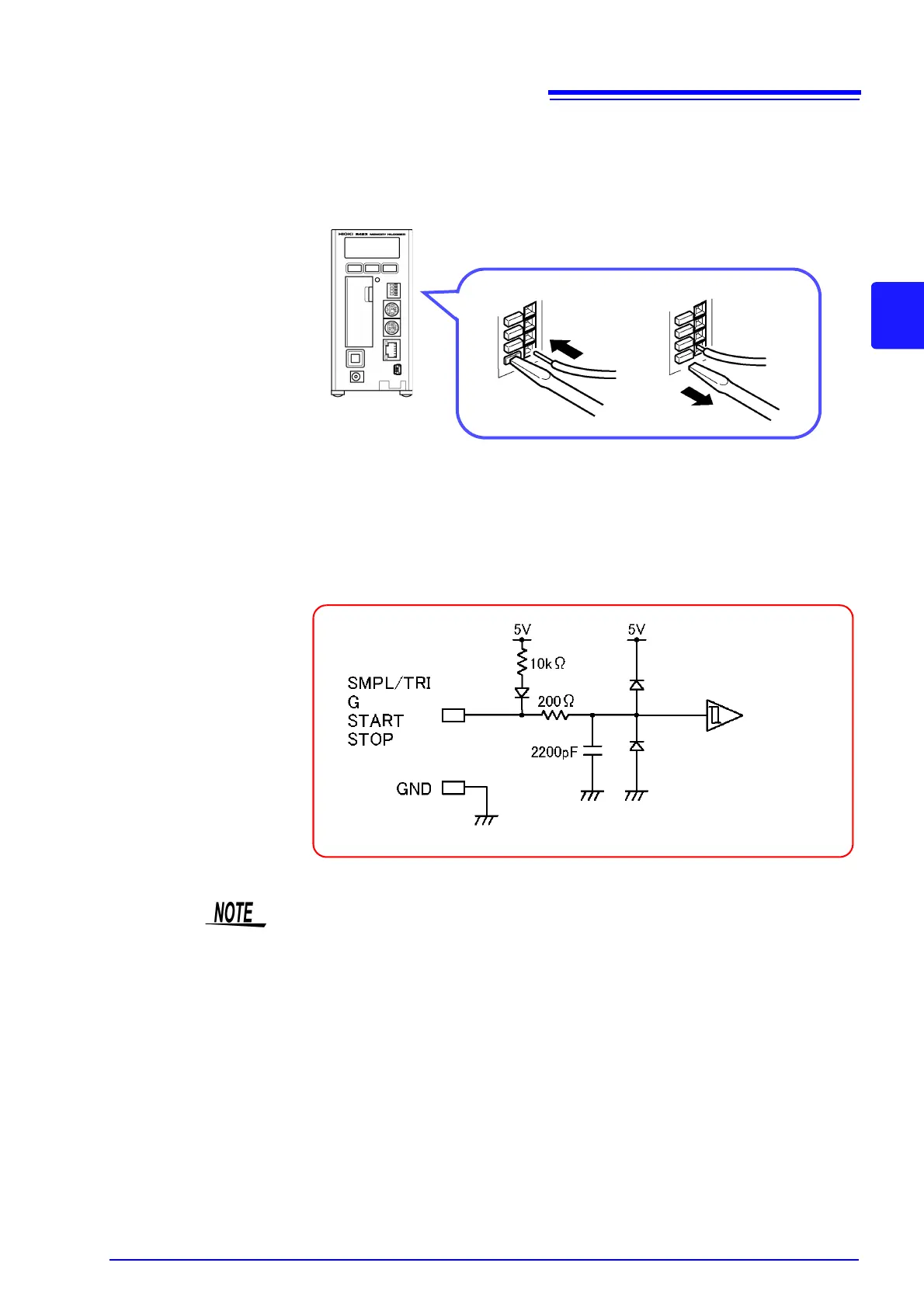
1. Press the button of the terminal with a flat blade screwdriver (or other
tool).
2. While keeping the button pressed in, insert the wire into the hole of the ter-
minal.
3. Release the button to lock the wire into place.
<Circuit Diagram of External Control Input Terminals>
* 10 μF when the chattering prevention filter is on.
*
When using multiple loggers to measure with the external sampling function,
care should be taken with the following points.
• Always connect the 9683 Connection Cables when synchronized measure-
ment will be performed. Furthermore, only use the SMPL/TRIG terminal for the
master.
• Disconnect the 9683 Connection Cables when synchronized measurement will
not be performed. Furthermore, input the same signal into the SMPL/TRIG ter-
minal of all loggers.