5.5 Setting the Trigger Function
117
5
Chapter 5 Setting Measurement Conditions
This section describes setting a trigger that uses a logic input signal. A logic trig-
ger can be set when the input type of the 8996 Digital/Pulse Unit is set to
[Logic].
(p. 95) Set the trigger pattern (1/0/x) and the AND/OR of the trigger pattern in
order to apply a trigger when a condition is satisfied. This can be set for each
channel.
1. Select the unit for which to set the trigger settings on the trigger settings
page. Select a pattern for the whole of the unit for which logic is selected.
If you want to reduce the number of display channels, use the narrow down fea-
ture to select the channels to display.
2. Select the trigger conditions.
3. Set the trigger pattern.
Clicking the
[All x], [All 0], or [All 1] button allows you to convert all selected logic
to the same value simultaneously.
5.5.7 Logic Triggers
A logic trigger is applied immediately if a trigger condition is satisfied at start
time.
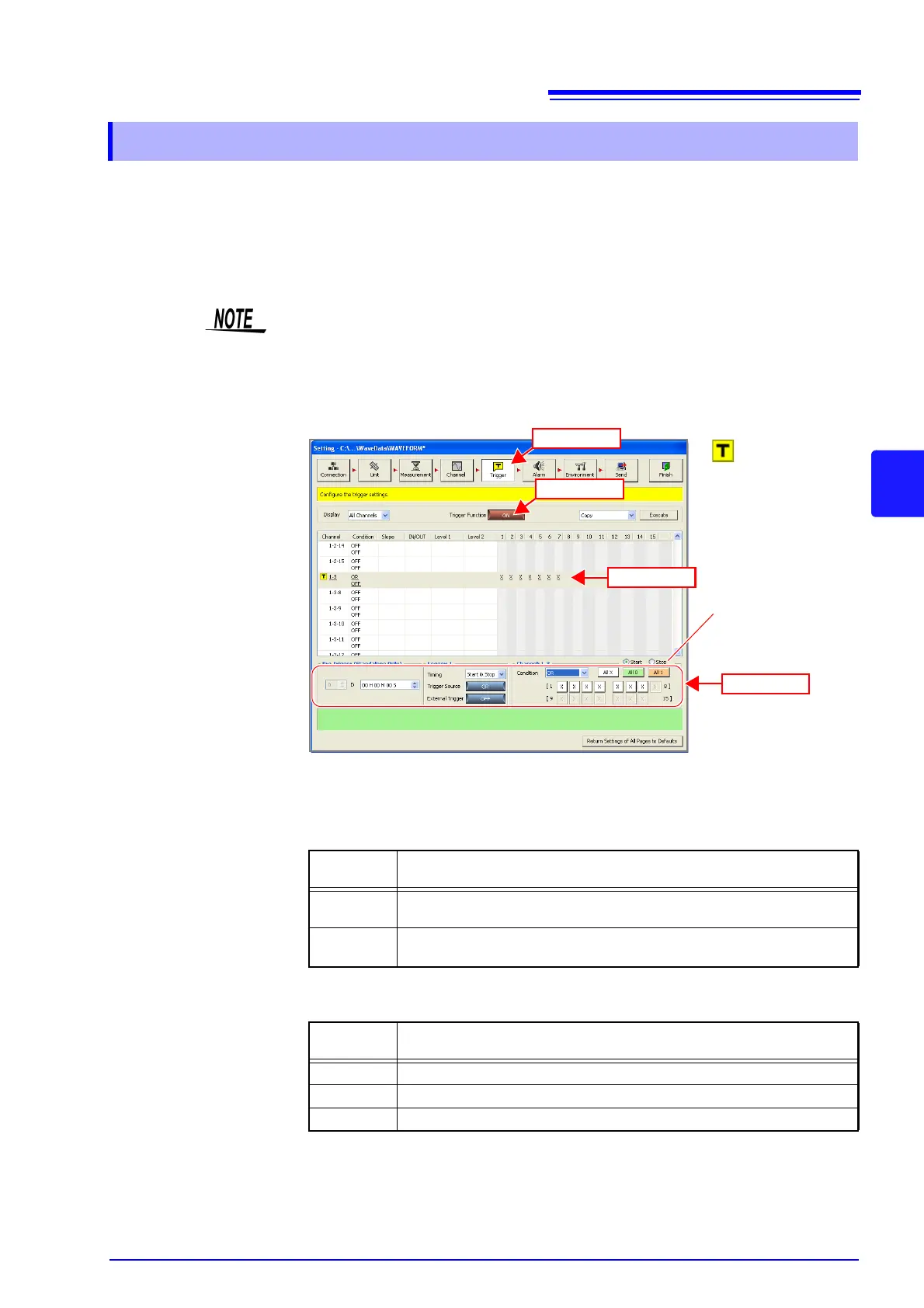
(1) Click
(3) Click
: Trigger On
(2) Click
When the trigger timing
is "Start & Stop," set
each of the start trigger
condition and stop trig-
ger condition.
(4) Set
Selectable
Items
Explanations
OR
A trigger is applied when any one of the trigger conditions set with the
pattern is satisfied.
AND
A trigger is applied when all of the trigger conditions set with the pattern
are satisfied.
Selectable
Items
Explanations
1 HIGH level signal
0 LOW level signal
x Ignore signal