5.5 Setting the Trigger Function
112
An analog trigger, logic trigger, and external trigger can be linked with AND/OR
logical operators. This sets the time relation between the satisfying of a condition
and the waveforms recorded. You can set AND/OR for each of start and stop.
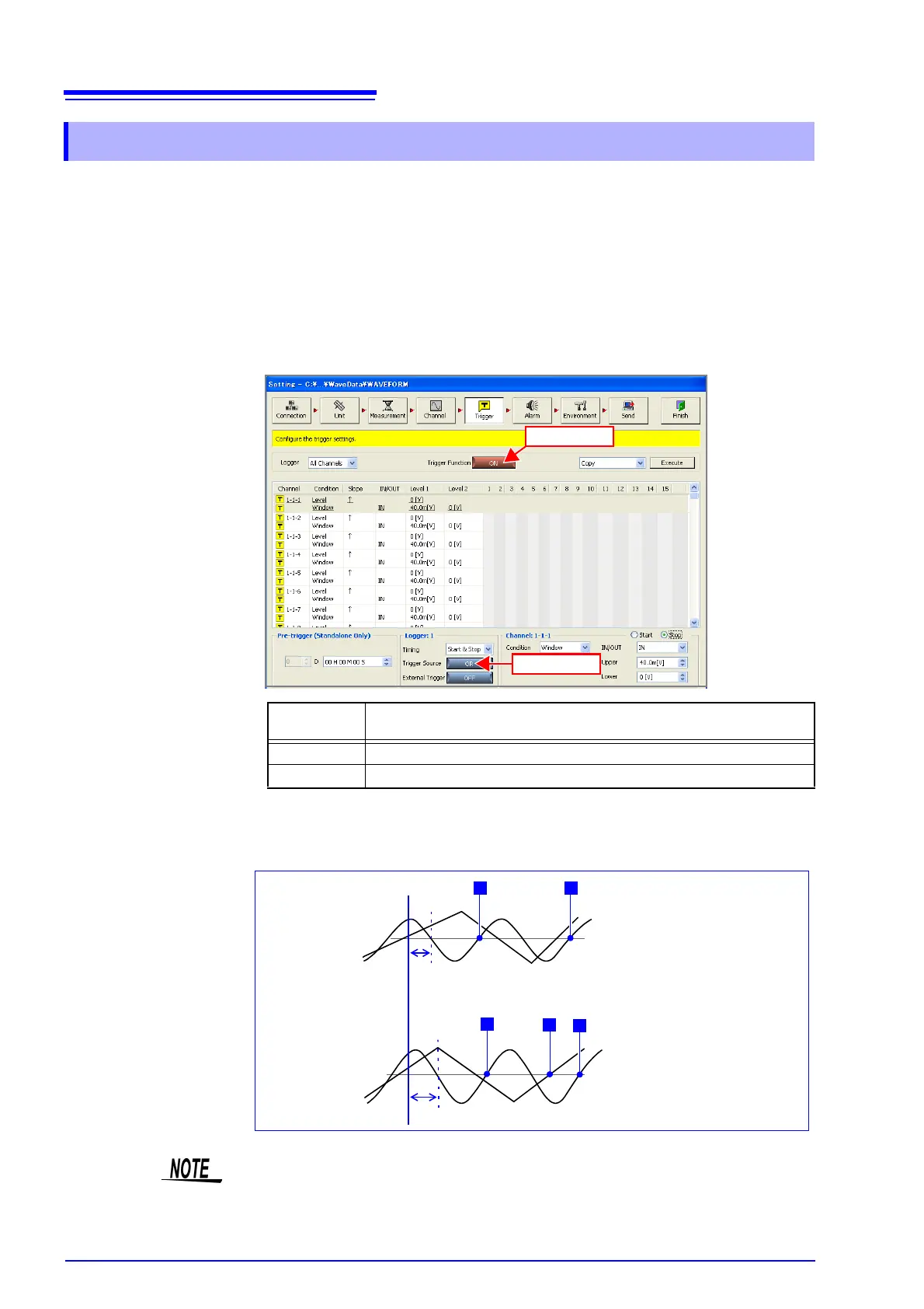
Set the trigger source condition for each logger.
1. Set the trigger function on the trigger settings page to ON.
Each click of the button toggles the trigger function ON and OFF.
2. Select the trigger source.
Each click of the button toggles the trigger source AND and OR.
If channel 1-1-1 and channel 1-1-2 are set to a level trigger of 0.00 V (
↑), a trig-
ger is applied for each of AND and OR as shown below. (p. 115)
5.5.4 Trigger Sources
Selectable
Items
Explanations
OR A trigger is applied when any one of the trigger conditions is satisfied.
AND A trigger is applied when all of the trigger conditions are satisfied.
[AND]
CH1-1-2
CH1-1-1
One waveform has crossed
above 0V as the other cross-
es on the upslope
[OR]
Either waveform crosses 0V
on the upslope
0 V
0 V
T
T
T
T
CH1-1-2
CH1-1-1
Start
T
A trigger is not applied if the trigger condition is already satisfied when measure-
ment starts. If the condition of one of the trigger sources is no longer satisfied
and then the condition is satisfied again, a trigger is applied.