5.5 Setting the Trigger Function
115
5
Chapter 5 Setting Measurement Conditions
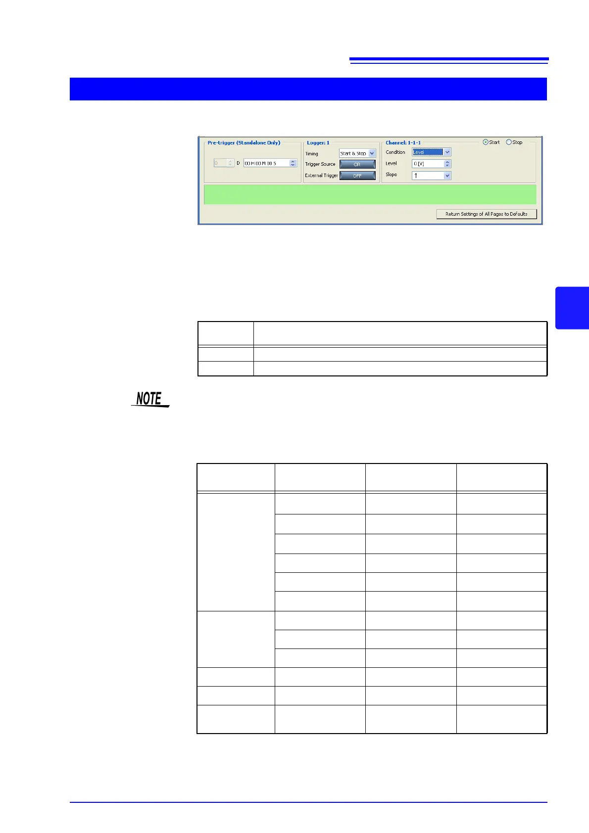
Set the level value and slope.
Level value:
Set the level value for applying a trigger. The scaling setting is reflected.
Slope:
Select the slope for when the input signal crosses the level value for applying a
trigger.
Trigger Resolution
When Level Trigger is Selected
Selectable
Items
Explanations
↑ A trigger is applied when the level value is crossed on the rising slope.
↓ A trigger is applied when the level value is crossed on the falling slope.
A trigger is not applied if the trigger condition is satisfied at start time.
Measurement
Object
Range Trigger Resolution Maximum Resolution
Voltage
100 mV f.s.
100
μV5 μV
1 V f.s. 1 mV
50
μV
10 V f.s. 10 mV
500
μV
20 V f.s. 20 mV 1 mV
100 V f.s. 100 mV 5 mV
1-5 V f.s. 10 mV
500
μV
Temperature
100°C f.s. 0.1°C 0.01°C
500°C f.s. 0.5°C 0.05°C
2000°C f.s. 2°C 0.1°C
Humidity 100%RH 0.1%RH 0.1%RH
Pulse totalization 1000 Mpulses f.s. 1 pulse 1 pulse
Pulse rotation rate 5000 [r/s]
1/ (Pulse rotation
rate) [r/s]
1/ (Pulse rotation
rate) [r/s]