3.2 Connecting a Cable to the Terminal Block
39
7
3
Chapter 3 Setting Up the Instrument
• The waveform for an open channel may sometimes appear to be influenced by
the signals of the other channels being measured. If you do not like this,
please set the waveform display of the open channel to OFF or short-circuit the
input terminals of the open channel by connecting the positive and negative
terminal.
• If an input cable of 3 m or longer is connected, measurement may be affected
by external noise and other electromagnetic interference.
• The general guidelines for resistance temperature detector terminations are pro-
vided in JIS Z 8704, in which A and B signals are designated by red and white
wires, respectively. However, the three-wire IEC guidelines define the connec-
tions differently (red and white are reversed), so special attention is required.
• The measurement current for a resistance temperature detector is 1 mA.
• Connect the cable while it is disconnected from the power line and ground wire.
• Be sure to close the terminal block cover, and tighten the screw.
• If the cable is connected in parallel with another device, there may be varia-
tions in the measurement values. When connecting in parallel, confirm opera-
tion before use.
• In the case of the SoL terminal (8949 Universal Unit only) for connecting a
resistance temperature detector or 9701 Humidity Sensor, all channels are
common internally and not insulated.
• Make sure the ambient temperature around the terminal block does not
change. In particular, make sure there is no ventilation fan, air conditioner, or
the like blowing air directly onto the terminal block.
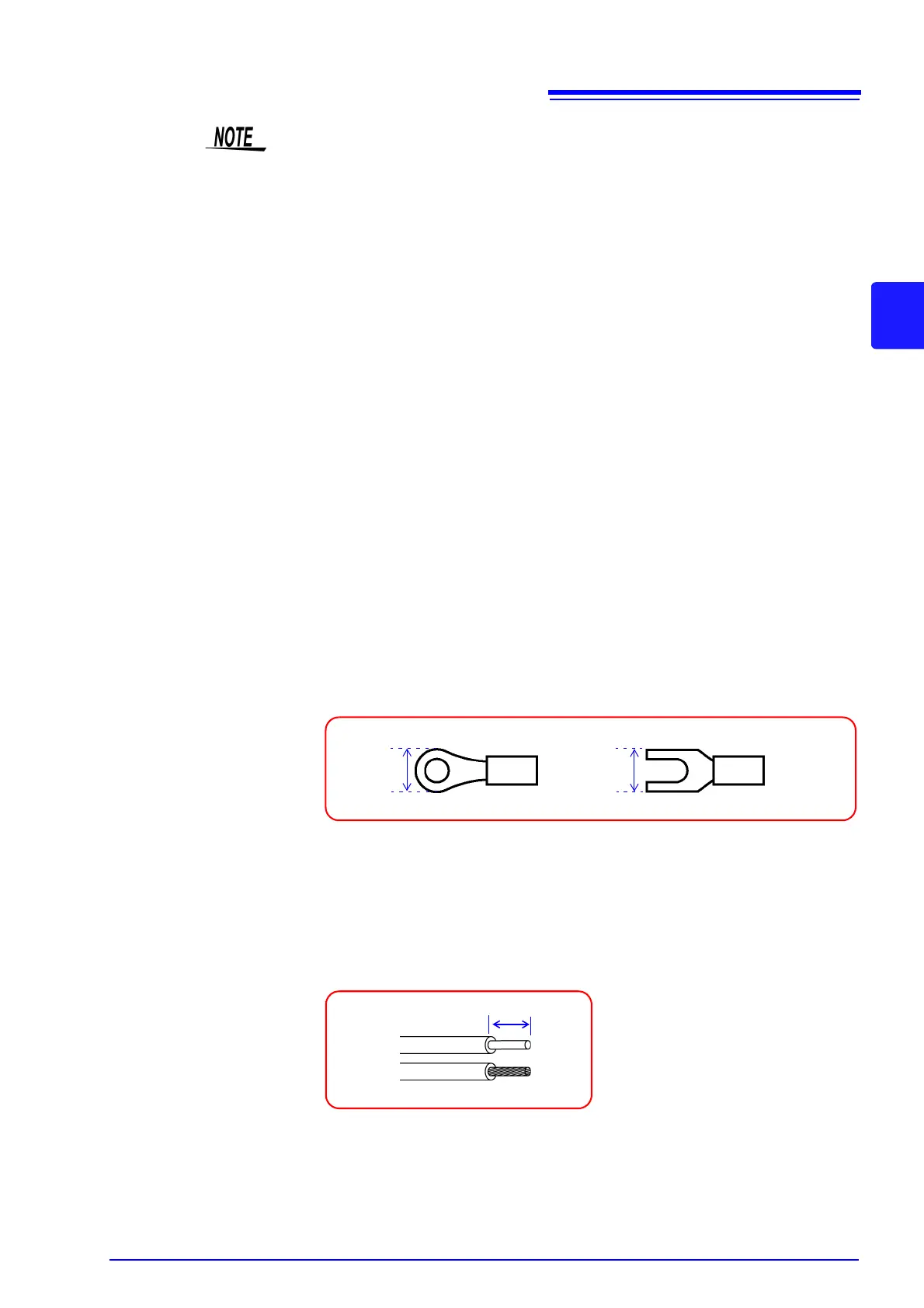
• When using crimp-type terminals for connecting to the terminal block of the
8948 Voltage/Temp Unit, 8996 Digital/Pulse Unit, or 8997 Alarm Unit, use ter-
minals with insulating coating that are for M3 screws and of the size shown in
the figure below.
• The following cable is recommended for connecting to the terminal block of the
8949 Universal Unit.
Single strand: 0.14 to 1.5 mm
2
Multi-strand: 0.14 to 1.0 mm
2
AWS: AWG26 to AWG16
Standard insulation stripping length: 5 mm
Single strand
Multi-strand
5 mm