PROPULSION / ENGINE 16-25
CHANGE C2 ICON A5 / MAINTENANCE MANUAL
insulting tape around the outside of the firewall flange and outside of inner tape wrap. Secure the
outer tape with hose clamps until a compression seal is achieved.
26. Remove any plugs and connect the two coolant hoses from right and left side of radiator, and
two coolant hoses at forward lower center of firewall bulkhead and install and tighten their band
clamps.
27. Fill the cooling system with COOLANT per the latest Rotax 912iS Maintenance Manual.
28. Connect the throttle cable to the engine throttle valve. Check and adjust throttle rigging. (See
“Inspect Throttle Control for Proper Travel and Security” on page 16-32.)
29. Remove any plugs and install oil feed hoses at thermostat. Torque B nuts to 150-250 in-lb.
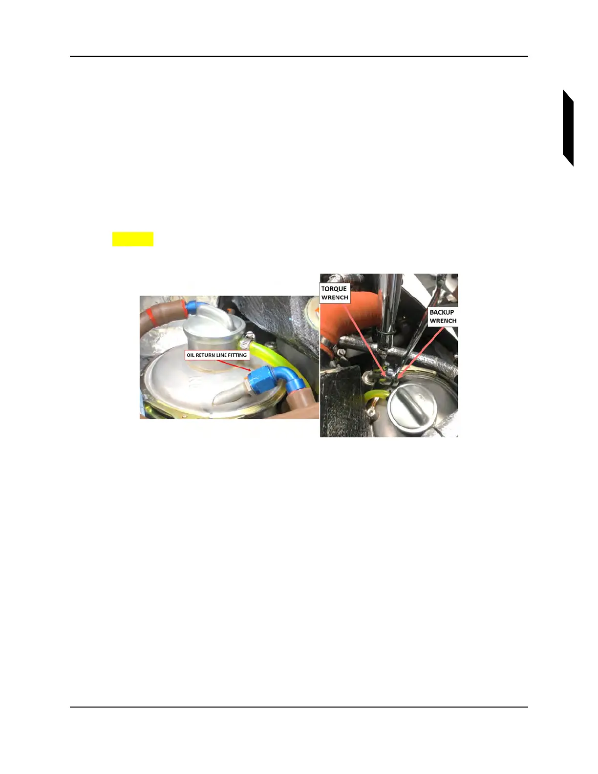
30. Remove plugs and install oil return hose at “IN” port of oil tank. (See Figure 16-14.) Torque B nut
to 300-350 in-lb if using Method A or 290-330 in-lb if using Method B. (See Figure 16-10.)
CAUTION: Ensure a back-up wrench is used on the oil tank fitting while
torqueing. Damage to oil tank may occur if it’s not used.
FIGURE 16-14
ENGINE OIL TANK RETURN HOSE FITTING TORQUEING AND 7/8” 12-POINT CROWS
FOOT SPECIAL TOOL
31. Install the propeller, extension and fan as an assembly onto the engine propeller flange with the
eight AN5C20A bolts and MS21043-5 nuts. Torque bolts in standard opposing sequence
(1-4-2-5-3-6), first torqueing all bolts to 110 in-lb, then 170 in-lb and finally, 230 in-lb. Recheck
torque of all bolts at 230 in-lb.
32. Fill the engine with correct quantity and type of oil. (See “Engine Oil Check and Replenish” on
page 16-77.)
33. Purge the engine oil system per the latest Rotax 912iS Maintenance Manual.
34. Remove any protective covering from throttle valve and install the induction air duct and install
and tighten its band clamps.
35. Remove any plugs and connect the -6 fuel supply and return lines at fuel rails. Torque fuel line
B-nuts (4 locations) to 99-117 in-lb.
36. Connect the AAPTS sensor connector (near induction air filter).
37. Connect the signal and ground wires at started solenoid. Torque M6 nuts to 36 in-lb.
38. Install the exhaust system and exhaust shields. (See “Install Exhaust System” on page 16-51.)