16-32 PROPULSION / ENGINE
ICON A5 / MAINTENANCE MANUAL CHANGE C2
3. Check ALL weld joints for cracks. Use a mirror and flashlight as required.
4. Check that hardware is secure. If necessary re-torque fasteners. See Figure 16-19.
a. Torque engine-mount-to-engine-block M10 screws to 355 in-lb (30 ft-lb).
b. Torque engine-mount-to-airframe bolts to 330-350 in-lb.
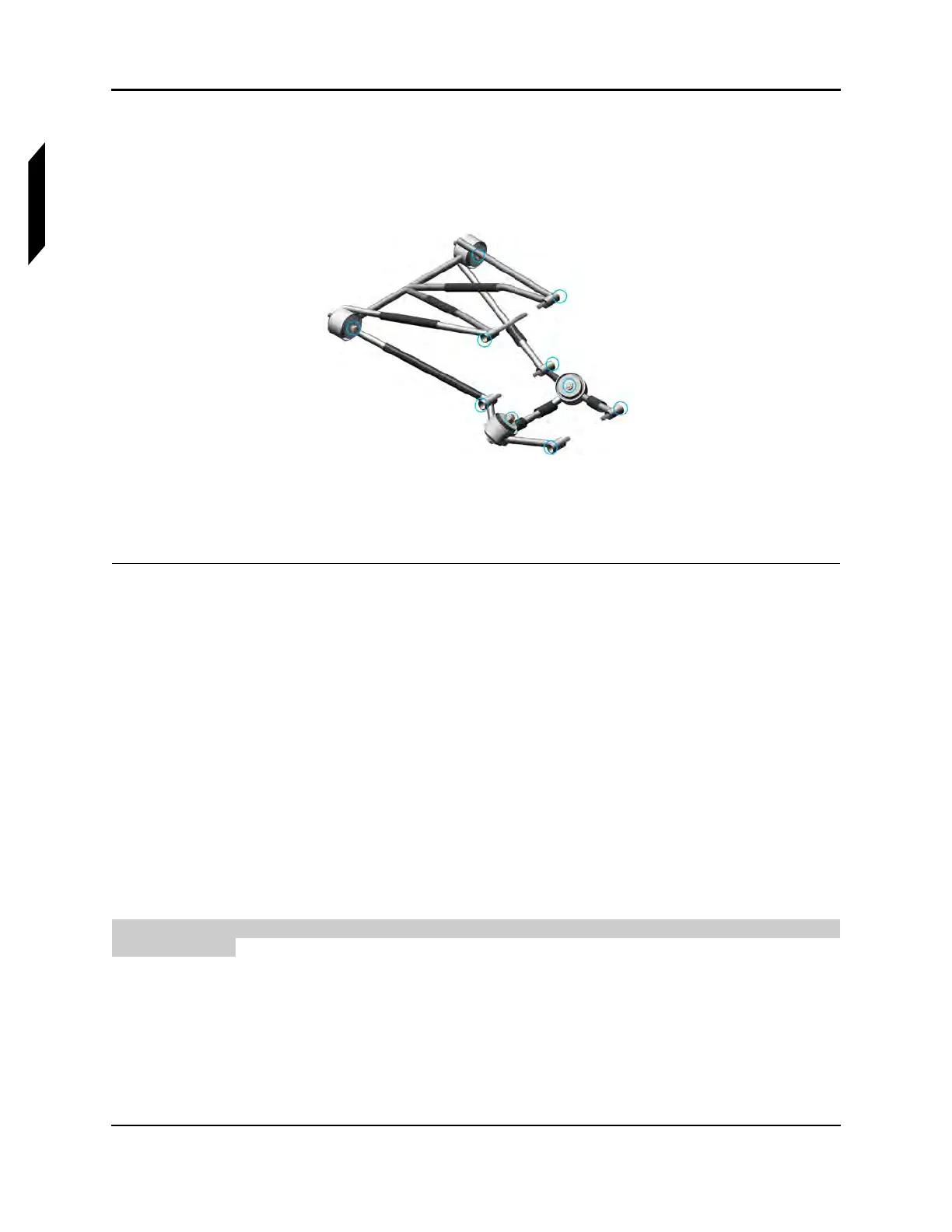
FIGURE 16-19
ENGINE MOUNT (RR, LH VIEW) WITH SCREW LOCATIONS CIRCLED IN BLUE
5. Reverse engine cowl instructions to install cowl, muffler, exhaust headers, and exhaust shields.
(See “Remove Engine Cowlings” on page 16-13.)
VERIFICATION METHOD:
Completion of the instructions above verify that the engine mount is acceptable.
RELATED INFORMATION:
"Condition and 100-Hour Inspection—Operational Inspection" on page 3-25
"Remove Engine Cowlings" on page 16-13
"Install Engine Cowlings" on page 16-16
"Remove Oil Tank" on page 16-72
"Install Oil Tank" on page 16-76
16.1.4.9 Inspect Throttle Control for Proper Travel and Security
Use the following to inspect throttle control for proper travel and security. Perform the inspection with
a second person.
TASK INFORMATION:
Type of Maintenance
Line
Level of Certification