Interactive SourceMeter® Instrument Reference Manual Section 3:
2461-901-01 A/November 2015 3-137
For this example, the same fail bit pattern is assigned to both the lower and upper bounds of the limits
so that resistors with resistance values in the range R-P% to R go into the same bin as those with
resistance values in the range R to R+P%. If you want to put parts in separate bins that correspond to
R-P% to R and R to R+P%, you can do so by assigning different bit patterns for the upper and lower
bounds of the limits.
Since the limits are inspected in ascending numeric order, the measured resistance is checked first
against Limit 2, which is the 20% limit. If a resistor fails this limit inspection, its resistance value is
outside of the 20% tolerance band and it is considered to be a bad part. The trigger model outputs the
Limit 2 fail bit pattern, which causes the component handler to place the resistor in the Bad Part bin.
If a resistor passes the 20% limit test, the resistance value is checked against the 10% limit value. If
the resistor fails this limit inspection, the resistance is outside of the 10% tolerance band, but in the
20% band. The trigger model outputs the Limit 3 fail bit pattern, which causes the component handler
to place the resistor in the 20% tolerance part bin.
If a resistor passes the 10% limit test, the resistance value is checked against the 5% limit value, and
so on. If a resistor passes all the limit tests, the trigger model outputs the overall pass bit pattern,
which causes the component handler to place the resistor in the 1% tolerance part bin.
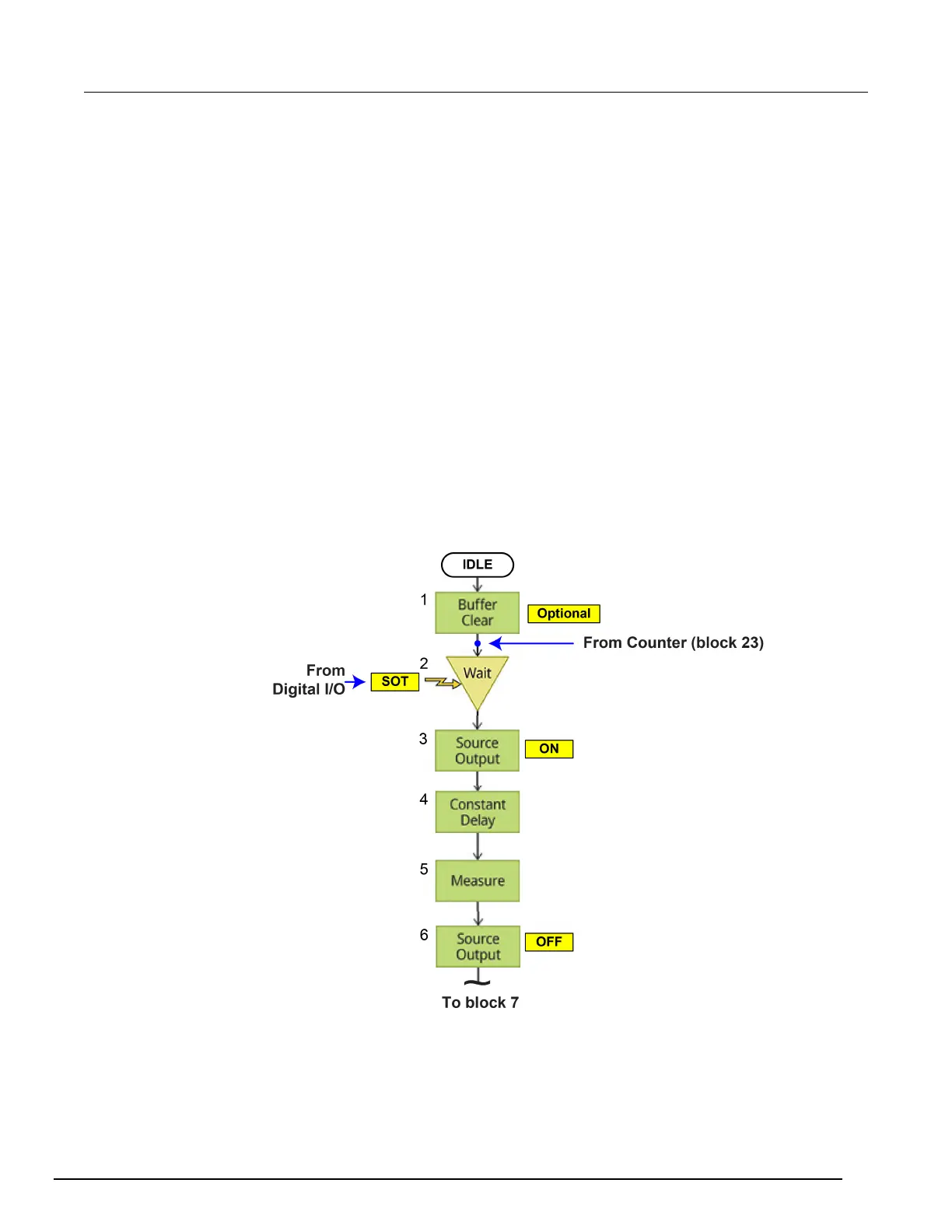
Resistor grading example
The following diagrams show the trigger model flow for the resistor grading example.
Figure 138: Resistor grading example blocks 1 to 6

 Loading...


