Interactive SourceMeter® Instrument Reference Manual Section 4: Source-
2461-901-01 A/November 2015 4-15
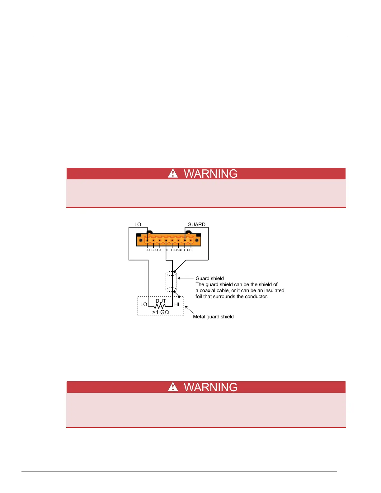
Guarding
Guarding is an effective way to reduce the leakage current and capacitance that can exist between HI
and LO. A guard is a low impedance point in the circuit that is at nearly the same potential as the high
impedance lead that is being guarded. Use guarding when you are sourcing or measuring low current
(less than 1 μA) or when test circuit impedance is more than 1 GΩ. Also use guard in noisy
environments.
The rear panel of the Model 2461 includes a current-limited (100 µA minimum) driven cable guard
designed to drive cable capacitance at the sense HI and force HI connections. This guard is always
enabled and provides a buffered voltage. For 2-wire measurements, guard is at the same level as the
force HI voltage. For 4-wire measurements, it is at the same level as the sense HI voltage.
To use the built-in guards of the Model 2461, you must use the rear-panel screw terminal connection.
There are no guards available on the front panel.
Guard is at the same potential as output HI. Therefore, if hazardous voltages are present at
output HI, they are also present at the GUARD terminal. Failure to heed this warning may
result in personal injury or death due to electric shock.
Figure 155: Model 2461 high-impedance guarding
Using guard with a test fixture
A test fixture is typically used when testing high-impedance devices. The test fixture reduces noise
and protects users from a potentially hazardous voltage on the guard shield.
To extend the guard to a test fixture, use a safety banana plug.
Connect the test fixture chassis to LO to reduce noise.
A safety shield must be used whenever hazardous voltages (>30 V RMS, 42 V peak) will be
present in the test circuit. To prevent electrical shock that could cause injury or death,
never use the Model 2461 in a test circuit that may contain hazardous voltages without a
properly installed and configured safety shield.

 Loading...


