Interactive SourceMeter® Instrument Reference Manual Section 4: Source-
2461-901-01 A/November 2015 4-5
If the voltage or current exceeds the limits, the instrument limits the source voltage to keep operating
currents and voltages in these boundaries. You can set operating limits to restrict current or voltage
more tightly than the operating boundary limits. In this drawing, the magnitudes are nominal values.
The specific maximum output magnitudes of the instrument are defined in the specifications. Also
note that the boundaries are not drawn to scale.
These operating boundaries are valid only if the instrument is being operated in an environment
where the ambient temperature is 30 °C (86 °F) or less. Above 30 °C, high power operation could
overheat the instrument, causing the output to turn off.
The four quadrants of the operating boundaries are defined as I, II, III, and IV. The Model 2461 can
operate in any of the four quadrants.
When the instrument is operating in quadrant I or III, the instrument is a source, which means that
voltage and current have the same polarity. As a source, the instrument is delivering power to a load.
When the instrument is operating in quadrant II or IV, the instrument is operating as a sink, which
means that voltage and current have opposite polarity. As a sink, the instrument dissipates the power
internally. An external source or an energy storage device, such as a battery, solar cell, or power
supply, can force operation in the sink region. The ability of the instrument to dissipate power is
defined by the boundaries shown in the following figures.
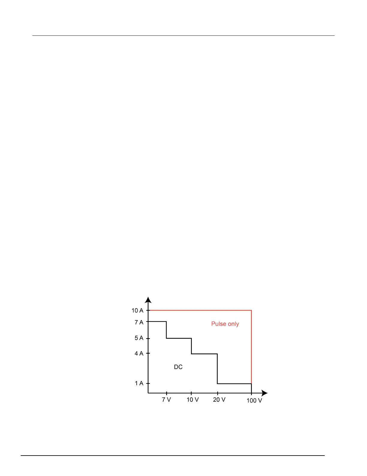
Current source operating boundaries
The operating boundaries for the current source are determined by the source range and limit
settings. The operating boundary is the lower of the two settings. For example, if the 100 mA current
source range is selected, the current source is limited to 105 mA, even if the source limit is set to 1 A.
The voltage limit line represents the actual limit that is in effect. These limit lines are boundaries that
represent the operating limits of the instrument for this quadrant of operation.
The operating point can be anywhere in or on these limit lines. The figure below shows operating
boundaries for the current source for quadrant I. Operation in the other three quadrants is similar.
The current source line is the maximum source value possible for the presently selected current
source range.
Figure 146: Model 2461 current source output characteristics

 Loading...


