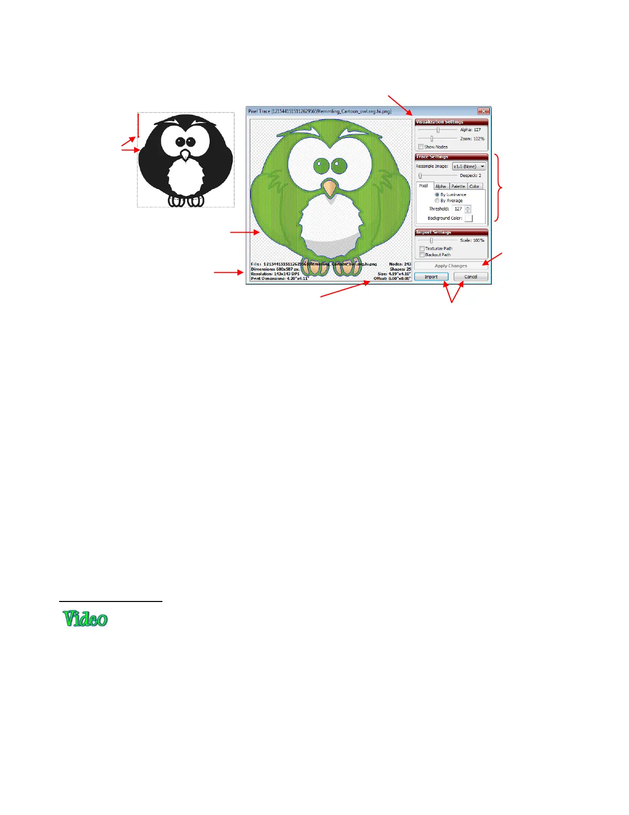
The image will open in the Pixel Trace window. Note the following information in this window:
When experimenting with the various tracing methods, remember the following:
Each time you change a setting, you need to click on the Apply Changes button to see the updated
preview.
Before beginning the Pixel Trace process, position your Caret in the top left part of the screen. You will
then also see a preview of the tracing on the main screen as you test different settings in the Pixel
Trace window. You many need to move the Pixel Trace window to see this tracing.
Experiment! Remember that you can change settings and refresh the results without making any
commitments. Take notes when you discover something new about tracing!
A combination of tracing methods might occasionally yield the best results. Each time you click on
Import, you will be given the opportunity to place the current trace into your main window, but then
return and try different settings or different methods. Be adventurous in your tracing! You can always
go back and delete parts of a trace you don’t like or duplicate tracings that are not as perfect as perhaps
one of the others. Chapter 7 contains methods for editing your tracings, as well.
For print and cut applications, mark the Texturize Path box so that the original raster graphic will also
be imported with the trace. You may also want to mark the Blackout Path box so that only the
outermost trace line will be imported.
Pixel Trace Method
The pixel trace is a monochromatic vectorization. In the Pixel Trace window, blue trace lines and green fills
will appear, regardless of the colors in the original image. These are defaults and can be changed by going
to View>Default Colors. After tracing, the tracings in the main window will be colored according to the
Virtual Mat color selected. They can be changed to other colors just like any other shapes.
The Threshold setting ranges from 1—255. Decrease this setting to add more distinction between colors
and increase the number of individual paths recognized and traced. Increase to lessen the distinction
between colors and decrease the number of individual paths recognized and traced. At the extreme of 255,
you will have nothing more than a box around the outside of the image being traced.
The following screenshots show the same image with different Threshold values used and the resulting
trace when imported onto the screen:
The blue lines indicate the trace
lines. The green is the fill that will
show up if the trace is accepted.
Information about the original
image: size, resolution, etc
Visualization Settings: adjust for personal preference only. These settings do not affect the trace.
results.
Information about the tracing: # of
nodes, size, number of paths, etc.
Import when ready or
Cancel trace process.
After each setting
change, click Apply
Changes to see new
trace.
Trace options and
settings (covered
in detail below)
On-screen
Preview will
appear at
current
location of
the Caret