210 Instruction Manual QuickTOC
®
ultra
IECEx 12E5119
9 Accessories and Options
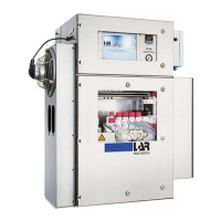
9.2 Reagent Cabinet LAR | PROCESS ANALYSERS AG
9.2.4 The carrier gas for the measurements must meet certain criteria (). Ambient air must be
conditioned accordingly if used. The tubing for the Ambient Air Preparation Unit is shown
below.
The installation of the air preparation unit depends on the installation variant carried out.
Variant 1 (without mounting):
Place the recirculating air treatment on the floor or on the PVC plate of the mounting rack under the ana-
lyzer.
Variant 2 (wall mounting):
Mount the recirculation system with the heavy duty anchors on the wall underneath the analyzer ().
Variant 3 (mounting rack):
9.2.4.1 Use the holes Q1 and Q2 of the mounting rack and the air preparation brackets Q1 and Q2
for mounting on the LAR mounting rackThe air preparation is supplied with a bypass of the
soda lime filter cartridge (left filter cartridge) and the activated carbon filter cartridge (right
filter cartridge). This prevents consumption of soda lime cookies with indicator.
Proceed with the tubing of the air preparation as shown in the tubing diagram and in :
1. Disconnect the hose (A) from the connector (1, ).
2. Feed the hose (A) through the point (6, ) into the recirculating air treatment.
3. Mount hose (A) in the circulating air treatment unit on the pressure regulator KH10 ().
4. Feed hose (C) (in circulating air treatment at the fine filter) through point (7) to the outside.
5. Mount hose (C) at point (1).
6. Hose (B) remains at points (2) and (3).
7. Route hose (D) from analyzer through point (9) to recirculation unit.