12E5119 Instruction Manual QuickTOC
®
ultra
IECEx 41
3 Product
3.7 Cooling and Emergency Cooling
LAR | PROCESS ANALYSERS AG
3.7.2.4 Relays
The analyser has eight isolated relays (switch contacts). They are capable of activating external circuits
up to 24V AC/DC with 1A, and can be assigned in the system software by the user. The relays can be
programmed as NCC (normally closed) or NOC (normally open). (The settings are in the software, NOC
is the default.) (Chapter 7.7.3 from page 108).
3.7.2.5 Analog outputs
The maximum apparent ohmic resistance for the isolated 0/4-20mA current loops is 500 Ohm. The type
of analog output (0-20 mA or 4-20 mA current loop) can be set in the software. If it is set to 4-20 mA, a
“Live-Zero” feature can be set in the system software. This means instrument faults are output with 0
mA. The conditions for the fault display can be programmed individually in the system software. On the
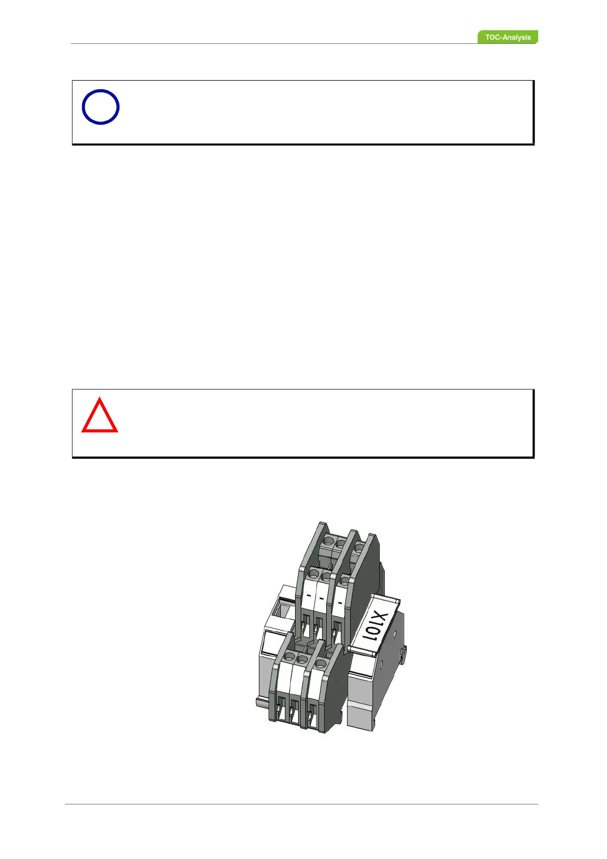
installation plate of the analyser (Fig. 25, page 36) is terminal strip X101 for the analog outputs (Fig. 29,
page 41).
The individual terminals of X101 are labelled. The first digit stands for the sample stream and the second
for the outgoing parameter.
.
Fig. 29: Analog outputs
Notice
The digital inputs are assigned to the corresponding sample streams. For an
overview, see Fig. 28, page 39.
Warning
Warning of damage of the analyser due to voltage or current on the analg
outputs!
No current or voltage must be applied to the analog outputs. LAR analysers
only output different currents in mA.
i
!