70 Instruction Manual QuickTOC
®
ultra
IECEx 12E5119
5 Start-up
5.11 Analyser Tubing LAR | PROCESS ANALYSERS AG
5.11 Analyser Tubing
Inside the analyser, samples, reagents and the carrier gas are transported from one component to the
next. Different tubes are used for this, which must be connected properly to the components.
Ensure for tubing that
• tubes are in perfect condition (e.g. no kinks)
• routing diagram is observed depending on configuration
• tubes are hand-screwed onto the screwed joints
• drain is depressurisedf
5.12 Electrical Connection of the Control Unit and the Relays
Connect the control unit F870S and the relays SR852 (two pieces) and SR853 according to the following
connection plan.
Notice
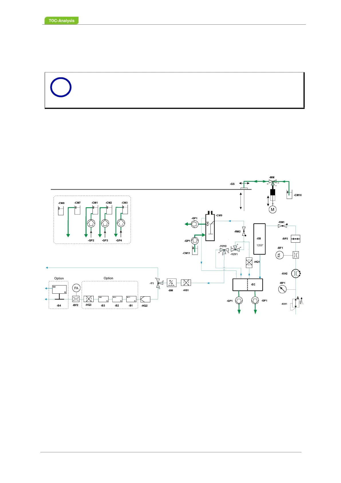
For tubing of your analyser, follow the flow diagram for your configuration (Chapter 12
from page 255).
Fig. 48: Flow Diagram (Example: TOC-Difference Method - 3 Sample Streams)
i