38 Instruction Manual QuickTOC
®
ultra
IECEx 12E5119
3 Product
3.7 Cooling and Emergency Cooling LAR | PROCESS ANALYSERS AG
3.7.2 Electronic Connections (Digital and Analog Connections)
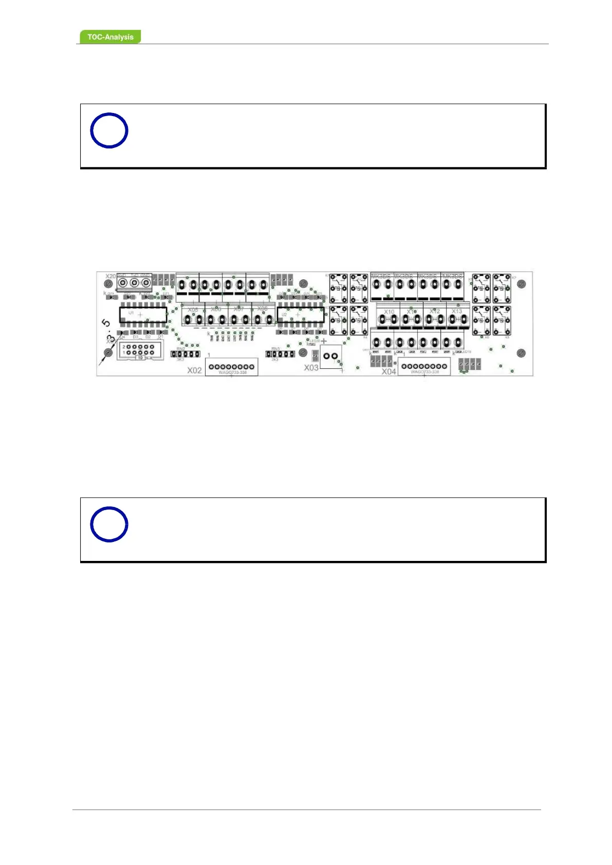
3.7.2.1 Connections on the TRC-Board
The analyser is fitted with a TRC board which is used to connect to external devices and/or process con-
trol systems. It is in the top left-hand side of the installation plate in the rear part of the housing (Fig. 25,
page 36). The rear part of the housing needs to be opened to access it.
Fig. 27: TRC-Board (complete)
The TRC-board has the following connections
• 1x RS 232 Serial interface
• 8x Digital inputs
• 8x Relays
Notice
Switch off the power supply prior to cabling.
Notice
A cable cross-section of 1.5 mm
2
= cable diameter of 1.4 mm can be used to
connect the signal lines to the TRC board.
i
i