12E5119 Instruction Manual QuickTOC
®
ultra
IECEx 221
9 Accessories and Options
9.3 Proceed analogously to the replacement of the soda lime in
LAR | PROCESS ANALYSERS AG
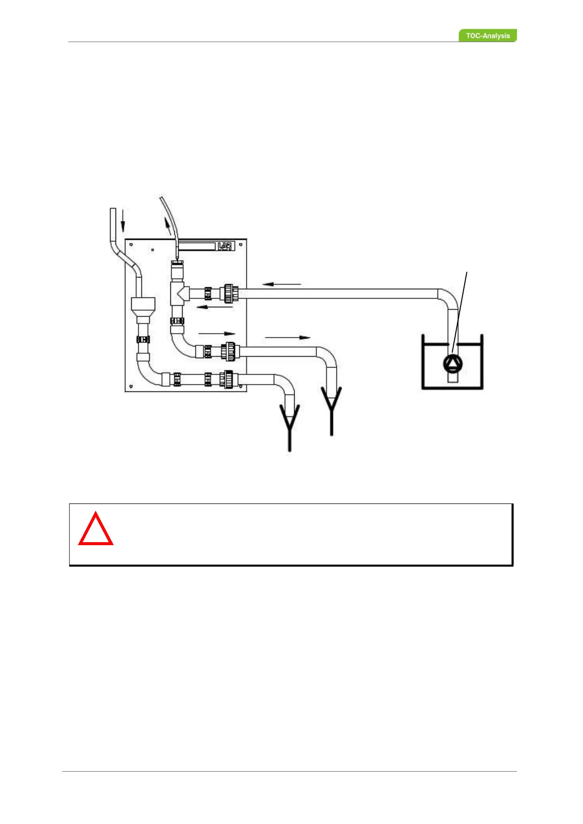
9.3.4 Installation of the FlowSampler
®
Ideally, LAR‘s FlowSampler
®
should be mounted immediately to the right of the analyser (e.g. on the
wall). So that the analyser drain inlet is at least 30 cm beneath the analyser.
The sample can be pumped for example with an immersion pump provided by the user. Depending on
the sample composition a cutting unit may be required. The immersion pump must ensure the required
flow rate of the FlowSampler
®
regarding to the distance.
9.3.5 Start-Up of the FlowSampler
®
1. Establish all connections to the analyser and sample.
2. Open the sample feed.
Fig. 143: Installation of the FlowSampler
®
Warning
The drain should be at least 30 cm beneath the analyser.
At the sampling pipe (needle) the sample must not be pressed out. Ideally, air
should be sucked into the FlowSampler
®
through the sampling pipe.
Analyser Drain
Analyser Inlet
Sample Inlet
Sample Outlet
Immersion Pump
(by User)
!