12E5119 Instruction Manual QuickTOC
®
ultra
IECEx 43
3 Product
3.7 Cooling and Emergency Cooling
LAR | PROCESS ANALYSERS AG
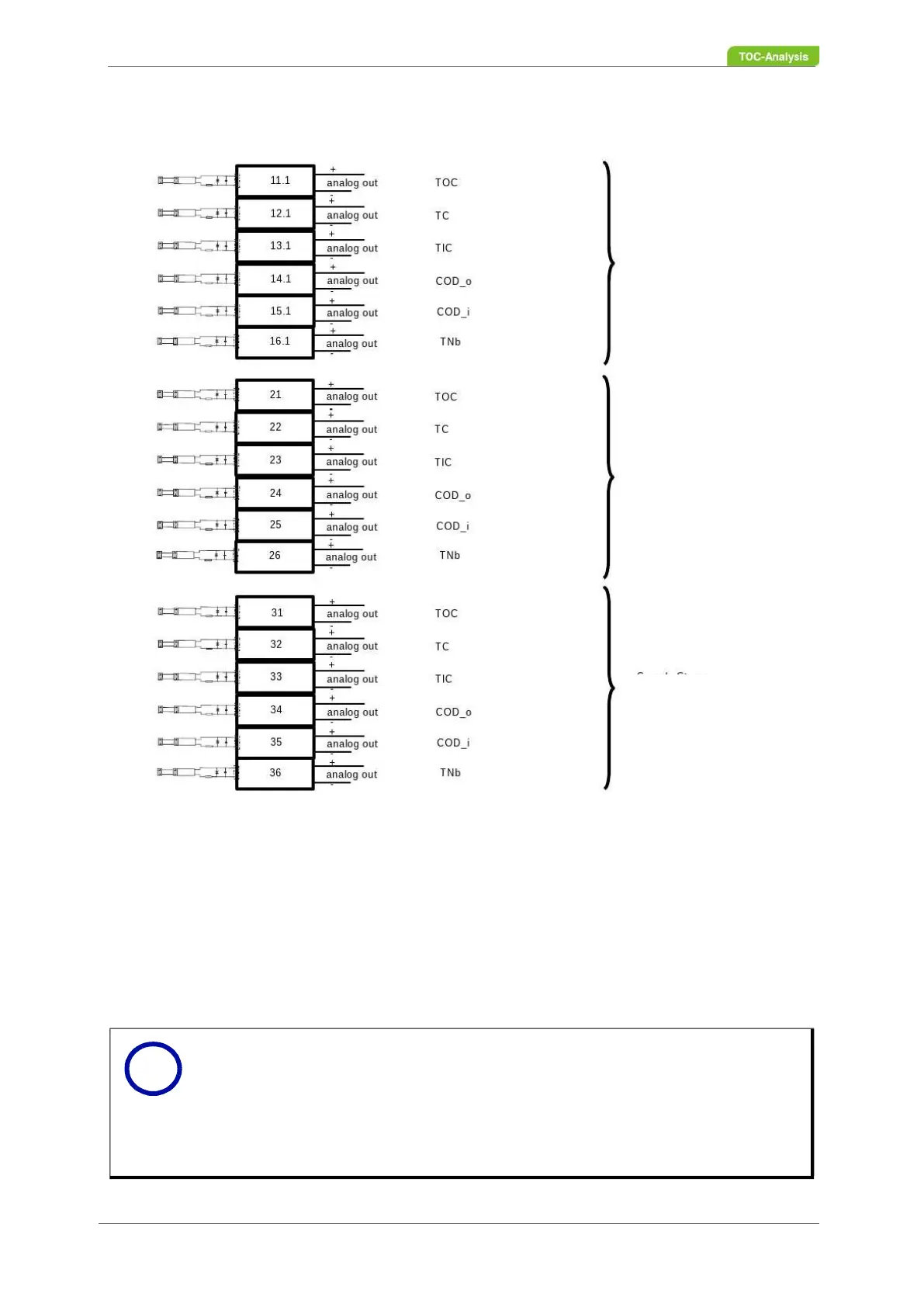
Fig. 31: Terminal Diagram (Part II) - programmable Analog Outputs
Notice
Please note that the terminal diagram (Fig. 30 - Fig. 32) is shown as an ex-
ample of the maximum configuration (six sample streams), and the analyser
ordered corresponds to your configuration.
The relays and analog outputs can be programmed individually by your local
partner or the Technical Support of LAR (Chapter 15 on page 283) as part
of the start-up.
Sample Stream
1
-
Measurement
2
-
Only for option
„Automatic
Ranging“
Sample Stream
2
Sample Stream
3
i