OPERATION
Disconnect the center-link as follows:
Hydraulic Lin k
13. If using hydraulic link, disconnect the center-link
as follows:
a. Pull up on latch (A), and position latch into notch
(B) on top of hook.
b. Release safety props on the header lift cylinders
(4.4.1 Header Safety Props, page 117).
c. Lower header down onto the transport wheels.
d. Disengage top link from the header. If necessary,
use the HEADER TILT switch to release load on
the cylinder.
Figure 4.38: Hydraulic Link
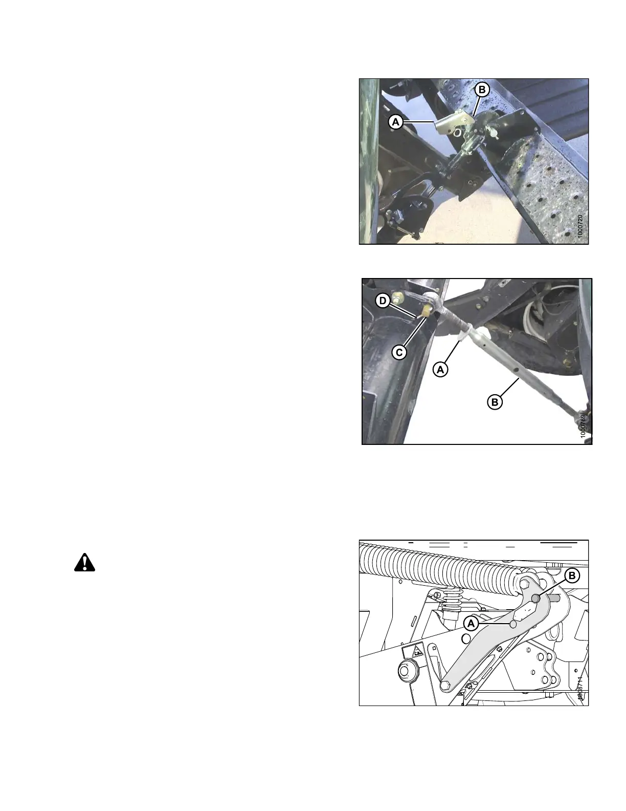
Mechanical Link
14. If using a mechanic
al lin k, disconne ct the center-lin k as
follows:
a. Loosen nut (A), an
d rotate barrel (B) to relieve load
on link.
b. Remove cotter pi
n (D) on pin (C), and remove
pin to disconnec
t from windrower. Reinstall pin
in header.
Figure 4.39: Mechanical Link
15. Back windrowe
r away from header.
16. Remove tow-ba
r sectio ns from storage locations on
header, assem
ble, and attach to header. Refer to
header opera
tor ’s manual.
Attach optional weight box to windrower as follows:
CAUTION
To prevent damage to the lift system when lowering
header lift linkages without a header or weight box
attached to windrower, ensure that float engagement
pin is installed in storage location (B) and NOT
installed at hole location (A).
Figure 4.40: Lif
tLinkage
169890 107 Revision A