OPERATION
If th e header is not le vel, perform the following checks prior to adjusting the lev elling lin kages.
NOTE:
The float springs are NOT used to level the header.
• Raise header t
o full height, and keep HEADER UP switch pressed to ensure lift cylinders are phased.
• Check drive w
heel tire pressures.
• Check and set
float adjustment. Refer to Checking Float, page 120.
To le ve l th e h
eader, follow these steps:
1. Place floa t p
ins in locked out location (A).
Figure 4.65: Float Pins
2. Park win
drower on level ground.
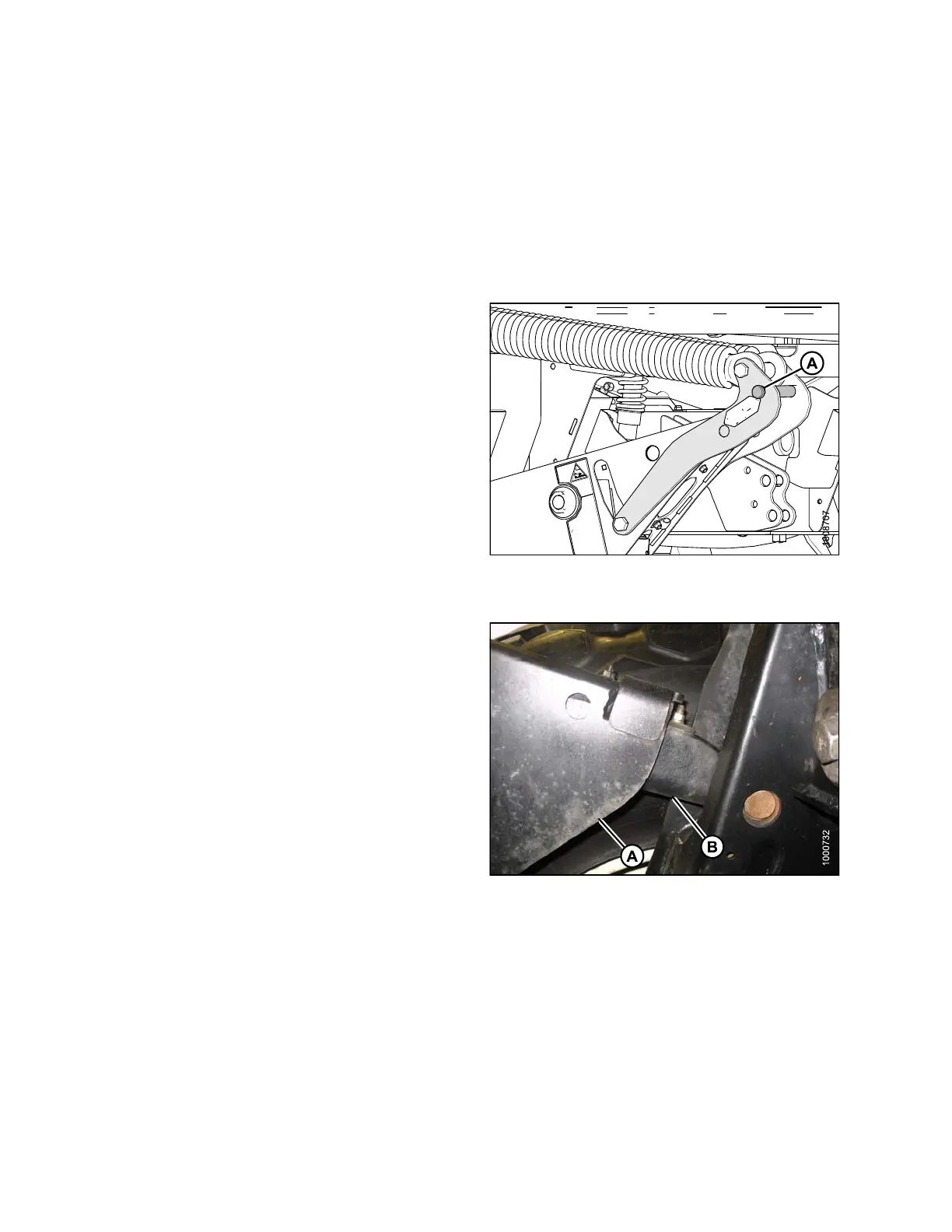
3. Set header approximately 6 in. (150 mm) off ground
and check that member (A) is against link (B). Note the
high and low end of header.
4. Place wooden blocks under header cutterbar and legs.
Figure 4.66: Lift Linkage
169890
1
22
Revision A