OPERATION
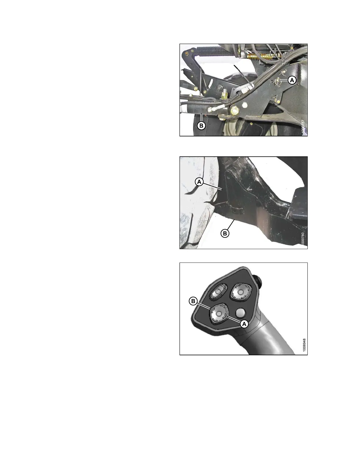
3. If necessary, relocat e pin (A) at the frame linkage as
required to raise the center-link (B) so that the hoo k is
above the attachment pin on the header.
IMPORTANT:
If the center-link is too low, it may contact the header as
the windrower approaches the header for hookup.
Figure 4.126: Hydraulic Center-Link without
Self-Alignm e nt Kit
4. Slowly drive the windrower forward so the feet (A)
on the windrower enter the boots (B) on the header.
Continue to drive s lowly forward until the feet engage
the boots and the header nudges forward.
Figure 4.127: Header Boot
5. Activate HEADER TILT cylinder switches on ground
speed lever (GSL) to extend or retract center-link
cylinder so that the hook lines up with the header
attachment pin.
6. Stop engine and remove key from ignition.
Figure 4.128: GSL
A-He
ader Tilt Up
B-He
ader Tilt Down
169890 150 Revision A