7-4 The Graphical Keypad
AC30V series Variable Speed Drive
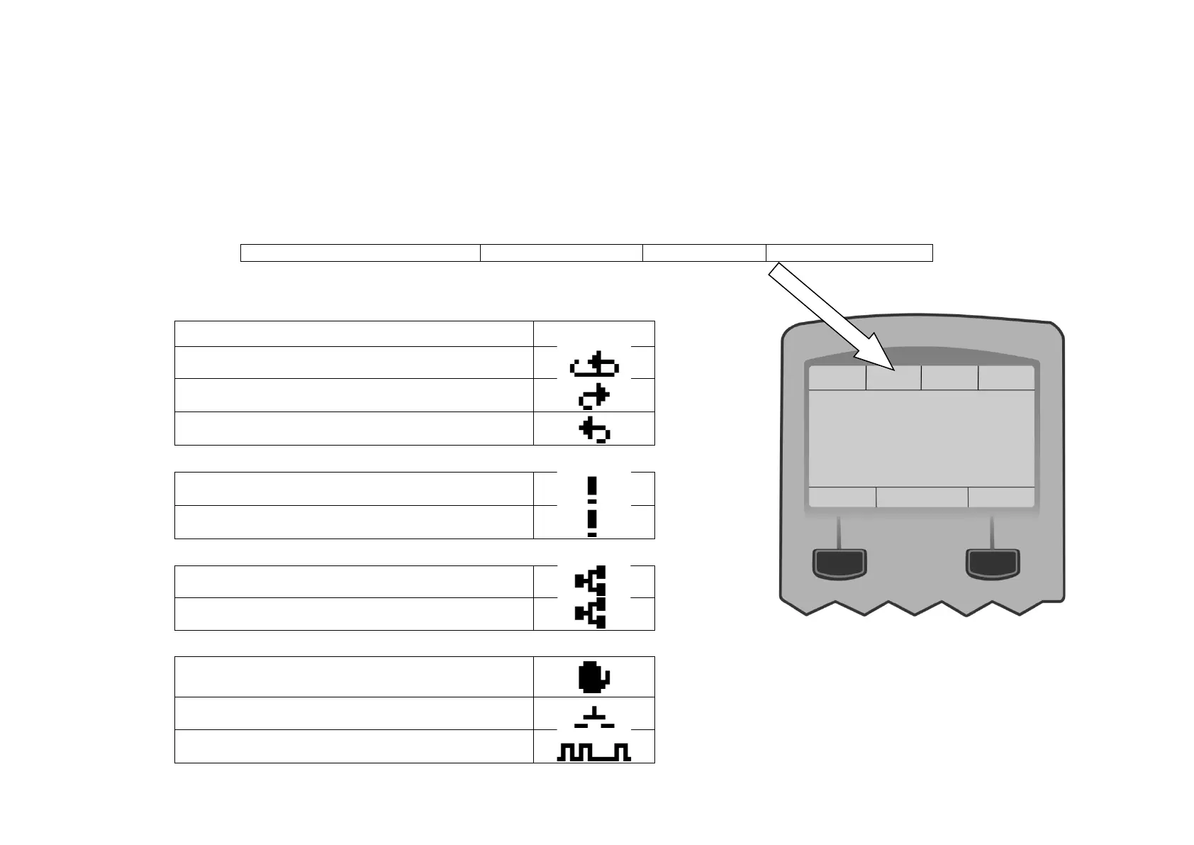
The Display
The display is divided into three areas. The top line shows a summary of the drive status, the centre region is the main work area and the bottom
line is used to indicate the action associated with the soft keys.
DRIVE STATUS SUMMARY
The top line of the display shows a summary of the drive status. This is divided into four regions. Each region is dedicated to a particular status
indication, as shown.
Left side Right side
The individual status conditions are indicated pictorially:
Run, Stop and Direction
Running in the positive direction
Running in the negative direction
Stopped, (ready to run in the positive direction)
Stopped, (ready to run in the negative direction)
Trip
Drive tripped, (indication flashing)
Warning
Ethernet
IP Address missing, (indication flashing)
IP Address configured
Control source
Start / stop control from the keypad
Start / stop control from the terminals
Start / stop control from a communications master
 Loading...


