Associated Equipment 5-4
AC30V series Variable Speed Drive
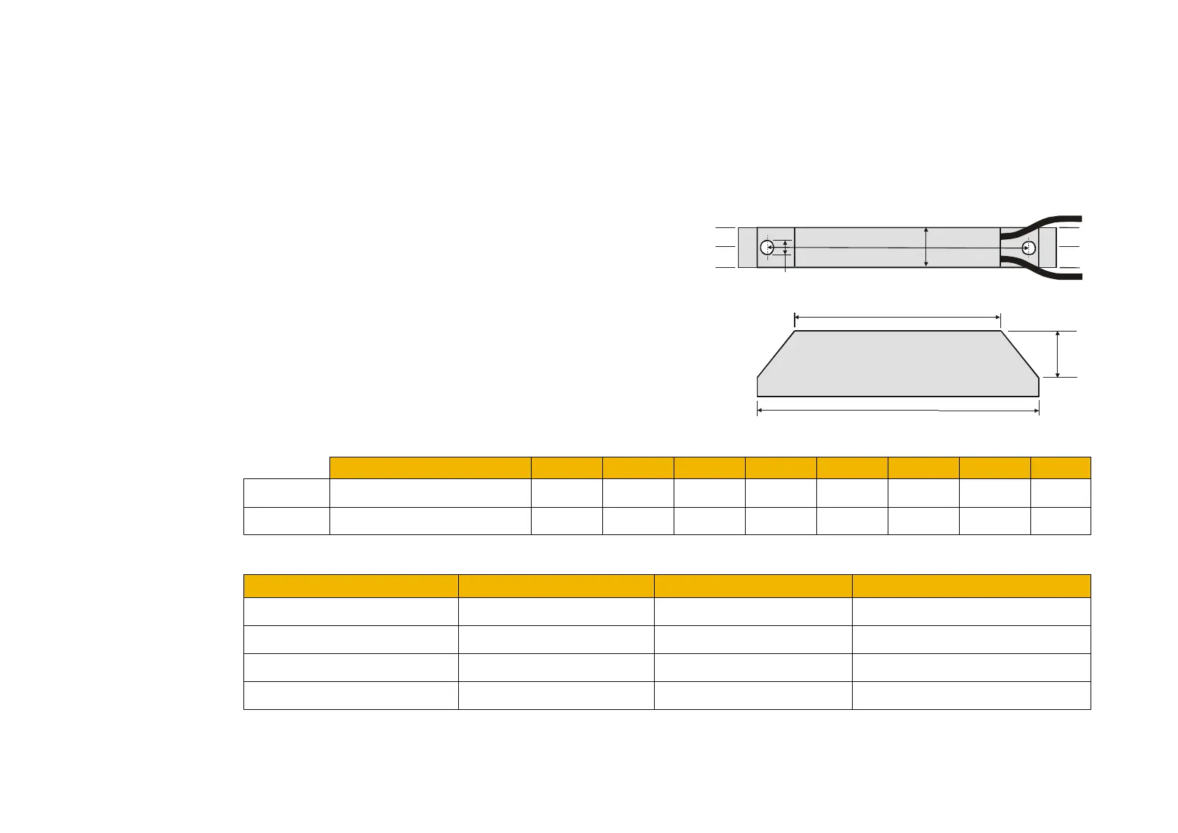
Dynamic Braking Resistors
These resistor sets are designed for stopping the system at rated power. They are rated for 10 seconds in a 100 seconds duty cycle.
See Appendix F for Minimum Brake Resistor value for each individual drive size.
RESISTOR SELECTION
These small, metal-clad resistors should be mounted on a heatsink (back
panel) and covered to prevent injury from burning.
There are four resistor values available.
The resistor can dissipate 10 x power rating for 5s, but the IMPORTANT
continuous rating should not be exceeded under repetitive loading.
500W
500 335 316 295 13 17 5.3 60 30
200W
500 165 146 125 13 17 5.3 60 30
Dimensions are in millimetres
Parker Part Number Power Rating (W)
Continuous Current Rating (A)
CZ467717 200 100 1.4
CZ463068 200 56 1.9
CZ467716 500 56 3.0
CZ388396 500 36 3.7
L1
H
flying leads
L2
L3
W
a
b
a
b
D
 Loading...


