6-23 Safe Torque Off
AC30V series Variable Speed Drive
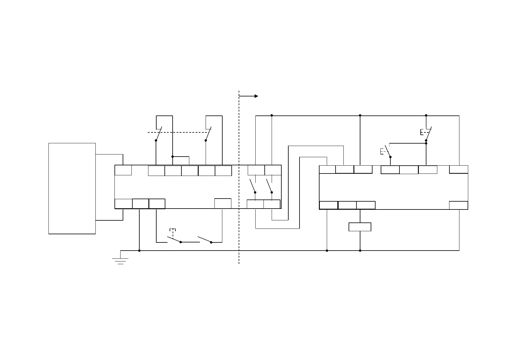
STO IMPLEMENTATION WITH SAFETY CONTROL UNIT
This example improves on the previous one by showing the resetting from a STO stop. The example shows wiring and terminal numbering for a
Siemens 3TK2827, but similar products are available from other vendors. Use of this Siemens part does not imply it is suitable for the user’s application.
The user must select and assess appropriate equipment.
Note: On power-up, the safety control unit outputs are OPEN; thus the STO state is requested of the AC30V. The latter responds by energising KA1 if both
channels are active and healthy. KA1 is used as a self-check for the reset cycle of the safety control unit. If a reset cannot be achieved due to KA1
being de-energised, a fault may be present and must be resolved by the user before relying on the STO function. See Fault Operation on page 6-14.
AC30V STO
SAFETY CONTROL UNIT
POWER
SUPPLY
THIS WIRING MUST BE WITHIN THE CONTROL CUBICLE.
 Loading...


