6-7 Safe Torque Off
AC30V series Variable Speed Drive
User Connections
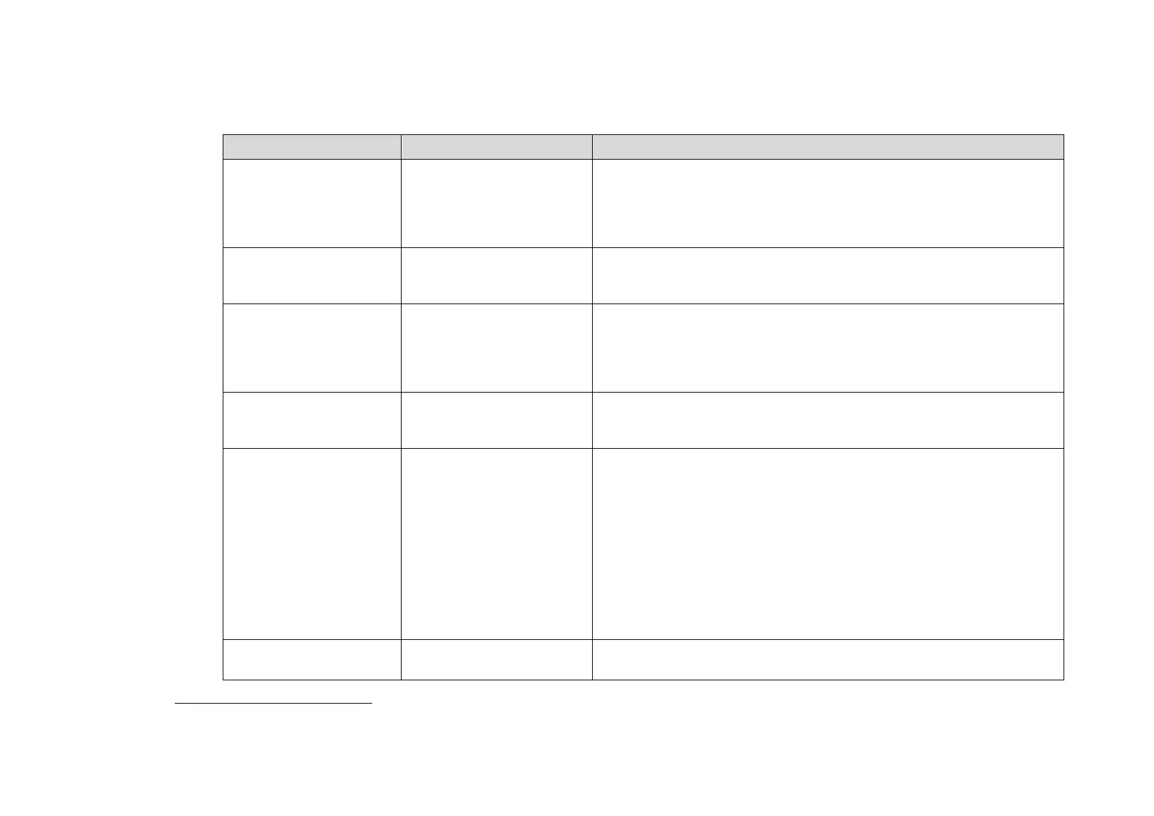
The STO terminals are on a 6-way terminal block X10. This is mounted on the AC30V control housing. Terminal designations are:
Terminal Number Terminal Name Description
X10/01 STO A Input
0V or not connected = drive will not run, STO is active on channel A.
24V = drive is enabled to run if X10/03 is also 24V.
This input is optically isolated from all other AC30V terminals except
X10/02, X10/03 and X10/04.
X10/02 STO Common
3
Signal return for STO A Input and STO B Input. Connected internally to
X10/04. This terminal or X10/04 must be connected to earth at one
common point in the drive system.
X10/03 STO B Input
0V or not connected = drive will not run, STO is active on channel B.
24V = drive is enabled to run if X10/01 is also 24V.
This input is optically isolated from all other AC30V terminals except
X10/01, X10/02 and X10/04.
X10/04 STO Common
2
Signal return for STO A Input and STO B Input. Connected internally to
X10/02. This terminal or X10/02 must be connected to earth at one
common point in the drive system.
X10/05 STO Status A
Together with X10/06, this terminal forms an isolated solid-state relay
output.
This output is ON (equivalent to closed relay contacts) when the STO
circuit is in the ‘safe’ state, i.e. the drive will not cause its motor to produce
torque.
However, this output should be used primarily as an indication. In the
unlikely event of a fault in the STO circuit, this output could turn on
erroneously to give a false indication of the STO status. It must not be used
as a guarantee that the motor will not produce torque.
The solid-state relay is protected by a self-resetting fuse.
X10/06 STO Status B
Together with X10/05, this terminal forms an isolated solid-state relay
output. See the description for X10/05.
3
Do not connect both X10/02 and X10/4 to earth, otherwise an earth loop could be created.
 Loading...


