EasyManuals Logo

Parker AC30 series User Manual

Parker AC30 series
453 pages
To Next Page IconTo Next Page
To Previous Page IconTo Previous Page
Page #88 background imageLoading...
Page #88 background image
6-21 Safe Torque Off
AC30V series Variable Speed Drive
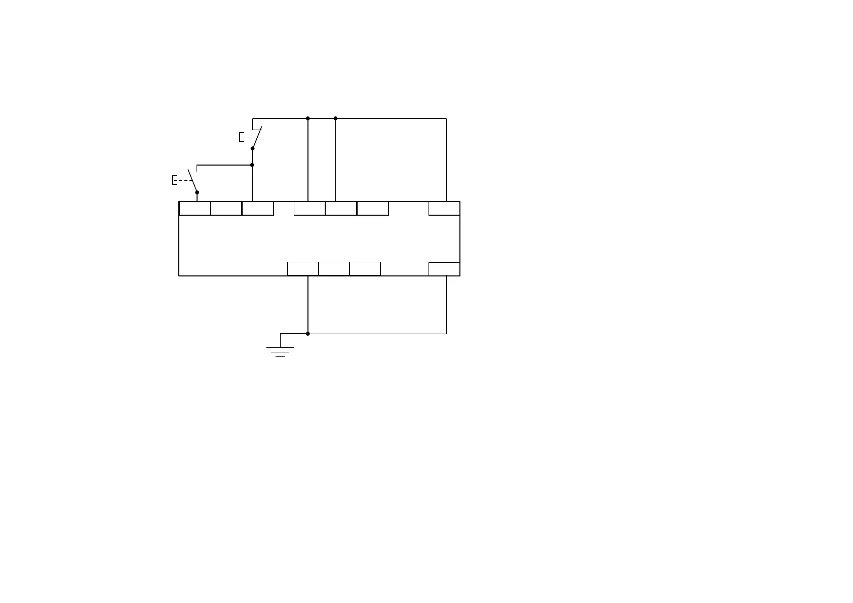
APPLICATIONS THAT DO NOT REQUIRE STO FUNCTION
Here the STO inputs X10/01 and X10/03 have been set to the inactive state (tied to +24V). Drive control is performed solely through software with no
inherent safety function. The drive is controlled with its own start and stop pushbuttons.
Note: Only X10/02 or X10/4 must be earthed, i.e. they should not both be earthed otherwise it is possible to create an earth loop.
STO inputs X10/01 and X10/03 must be
connected to 24VDC with respect to
terminals X10/02 or X10/04.
STO Status output on X10/05 and X10/06
may be left disconnected.
All wiring shown is within the control cubicle.
DRIVE
START
DRIVE
STOP
24VDC
X13/02
X12/01
X10/01
X10/03
X10/06
X12/05
X12/06
X10/05
X10/04
X10/02
www.comoso.com

Table of Contents

Other manuals for Parker AC30 series

Questions and Answers:

Question and Answer IconNeed help?

Do you have a question about the Parker AC30 series and is the answer not in the manual?

Parker AC30 series Specifications

General IconGeneral
Control ModesClosed-loop vector
FeedbackEncoder
Operating Temperature0 to 40°C (32 to 104°F) standard, -20 to 50°C (-4 to 122°F) with derating
ProtectionOvercurrent, Overvoltage, Undervoltage
CommunicationRS485

Related product manuals