Compliance C-14
AC30V series Variable Speed Drive
CABLING REQUIREMENTS
Refer to “Recommended Wire Size” page C-35 for calculating wire sizes.
Cable Routing
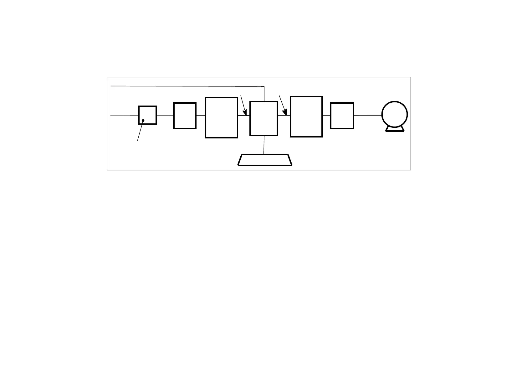
drive
filter
motor
brake resistor
(noisy)
(noisy)
signal/control
cable
(sensitive)
power
supply
(clean)
cable
ac
fuse or suitable
circuit breaker
(RCD not
recommended)
line
choke
(noisy)
motor
cable
supply
EMC
motor
choke
(noisy)
filter
motor
output
external
EMC
Figure C-2 Cabling Requirements
Cables are considered to be electrically sensitive, clean or noisy. You should already have planned your cable routes with respect to segregating
these cables for EMC compliance.
• Use the shortest possible motor cable lengths.
• When connecting multiple motors to a single VSD, use a star junction point for motor cable connections. Use a metal box with
entry and exit cable glands to maintain shield integrity.
• Keep electrically noisy and sensitive cables apart.
• Keep electrically noisy and sensitive parallel cable runs to a minimum. Separate parallel cable runs by at least 0.25 metres. For
runs longer than 10 meters, separation should be increased proportionally. For example if the parallel runs were 50m, then the
separation would be (50/10) x 0.25m = 1.25m.
• Sensitive cables should cross noisy cables at 90°.
• Never run sensitive cables close or parallel to the motor, dc link and braking chopper circuit for any distance.
• Never run supply, dc link or motor cables in the same bundle as the signal/control and feedback cables, even if they are
screened.
• Ensure EMC filter input and output cables are separately routed and do not couple across the filter.

 Loading...


