5-5 Associated Equipment
AC30V series Variable Speed Drive
Calculation
Brake resistor assemblies must be rated to absorb both peak braking power during deceleration and the average power over the
complete cycle.
J - total inertia (kgm
2
)
n
1
- initial speed (rpm)
Average
braking power
P
P
t
av
pk
c
=
x t
b
n
2
- final speed (rpm)
t
b
- braking time (s)
t
c
- cycle time (s)
Obtain information on the peak power rating and the average power rating of the resistors from the resistor manufacturer. If this
information is not available, a large safety margin must be incorporated to ensure that the resistors are not overloaded.
By connecting these resistors in series and in parallel the required braking capacity can be selected for the application.
The minimum resistance of the combination and maximum dc link voltage must be as specified in Appendix F: IMPORTANT
“Technical Specifications” - Internal Dynamic Brake Switch.
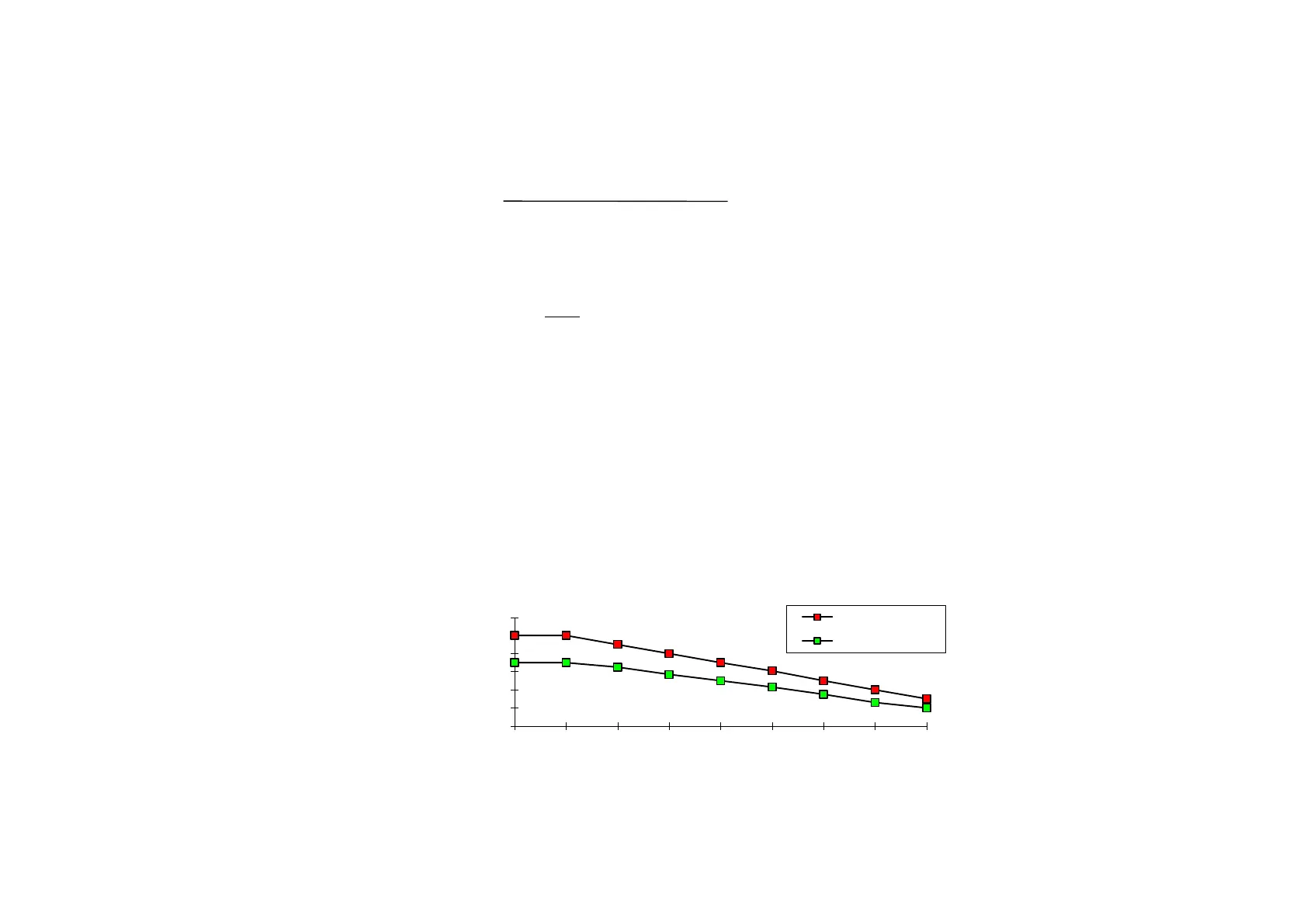
Figure 5.2 Braking Resistor Derating Graph (Metal Clad Resistors)
0
20
40
60
80
100
120
0 25 50 75 100 125 150 175 200
% of Rated Power
Ambient Temp (C)
Resistor Derating Graph
chassis mounted
free air

 Loading...


