D-70 Parameter Reference
AC30V series Variable Speed Drive
PNO Parameter Descriptions
1931 PID Output Filter TC
In order to help attenuate high frequency noise on the PID output, a first order output filter has been provided. This parameter
determines the output filter time constant.
1932 PID Output Pos Limit
The maximum positive excursion (limit) of the PID output.
1933 PID Output Neg Limit
The maximum negative excursion (limit) of the PID output.
1934 PID Output Scaling
The overall scaling factor which is applied after the positive and negative limit clamps
1935 PID Output*
PID output monitor
1936 PID Error*
PID error monitor. This is Setpoint – Feedback.
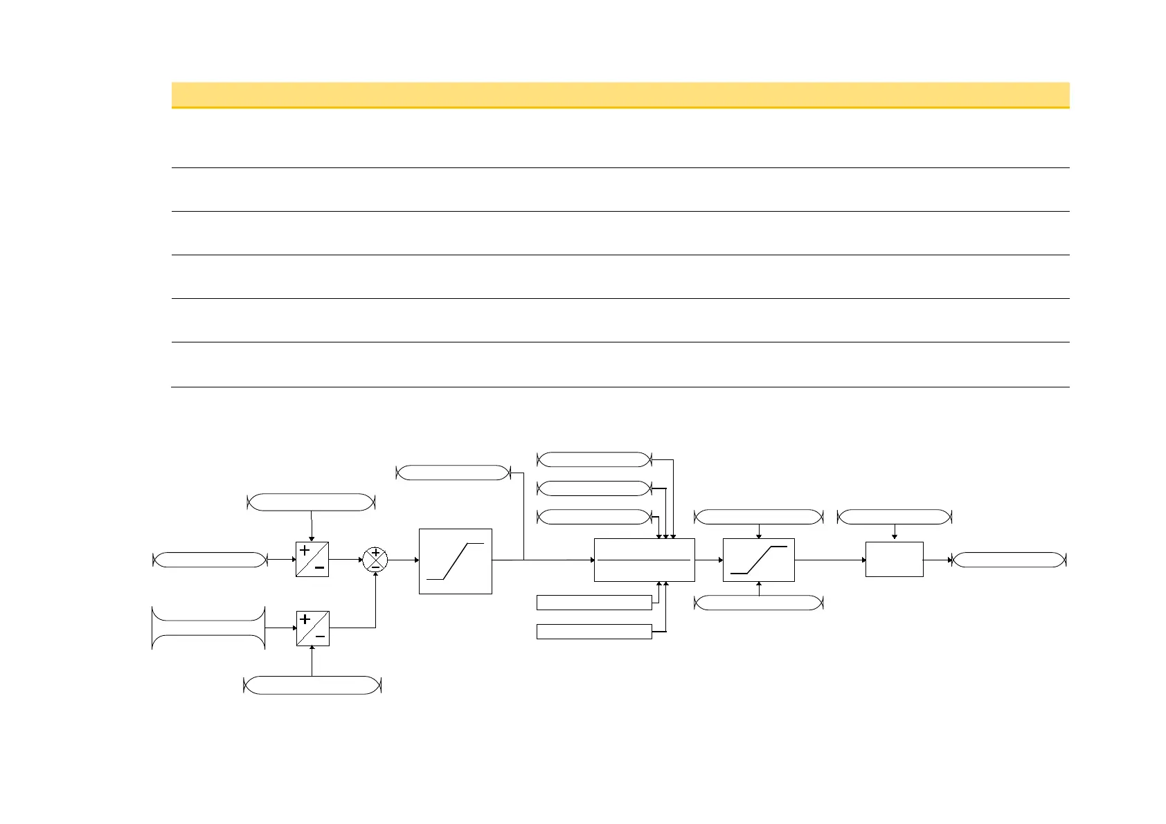
Functional Description
Kp(1+sTi)(1+sTd)
sTi(1+sTf)
D TIME CONST
I TIME CONST
P GAIN
ENABLE
INTEGRAL DEFEAT
X
PID OUTPUT
OUTPUT NEG LIMIT
OUTPUT POS LIMIT
OUTPUT SCALING
SETPOINT
FEEDBACK
SETPOINT NEGATE
FEEDBACK NEGATE
+100.00%
-100.00%
PID ERROR
sign change
sign change

 Loading...


